Eureka AIR delivers breakthrough ideas for toughest innovation challenges, trusted by R&D personnel around the world.

Drilling and drilling completion method for interior of shale reservoir in drilling engineering

A technology for shale reservoirs and drilling engineering, which is applied to drilling equipment and methods, drilling equipment, drill bits, etc., and can solve the problems of slow drilling time, high risk of casing running, and difficulty in tripping and running after drilling.

Active Publication Date: 2019-03-19
滦平县伟源矿业有限责任公司
View PDF10 Cites 4 Cited by
  • Summary
  • Abstract
  • Description
  • Claims
  • Application Information

AI Technical Summary

Problems solved by technology

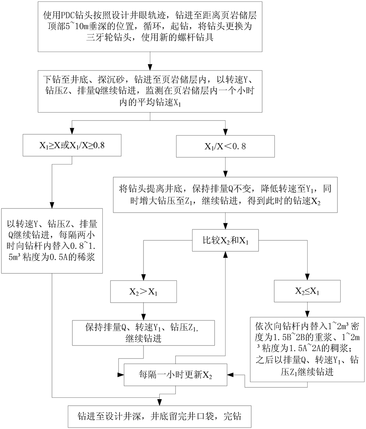
[0006] The object of the present invention is to provide the method for drilling and completing the drilling in the shale reservoir in the drilling engineering, to solve the slow and low drilling speed in the prior art when drilling in the shale reservoir; The problem of high casing risk is realized to increase the drilling speed in shale reservoirs, improve engineering efficiency; reduce operational risks and improve the safety factor of casing

Method used


Image

  • Drilling and drilling completion method for interior of shale reservoir in drilling engineering
  • Drilling and drilling completion method for interior of shale reservoir in drilling engineering

Examples


Embodiment 1

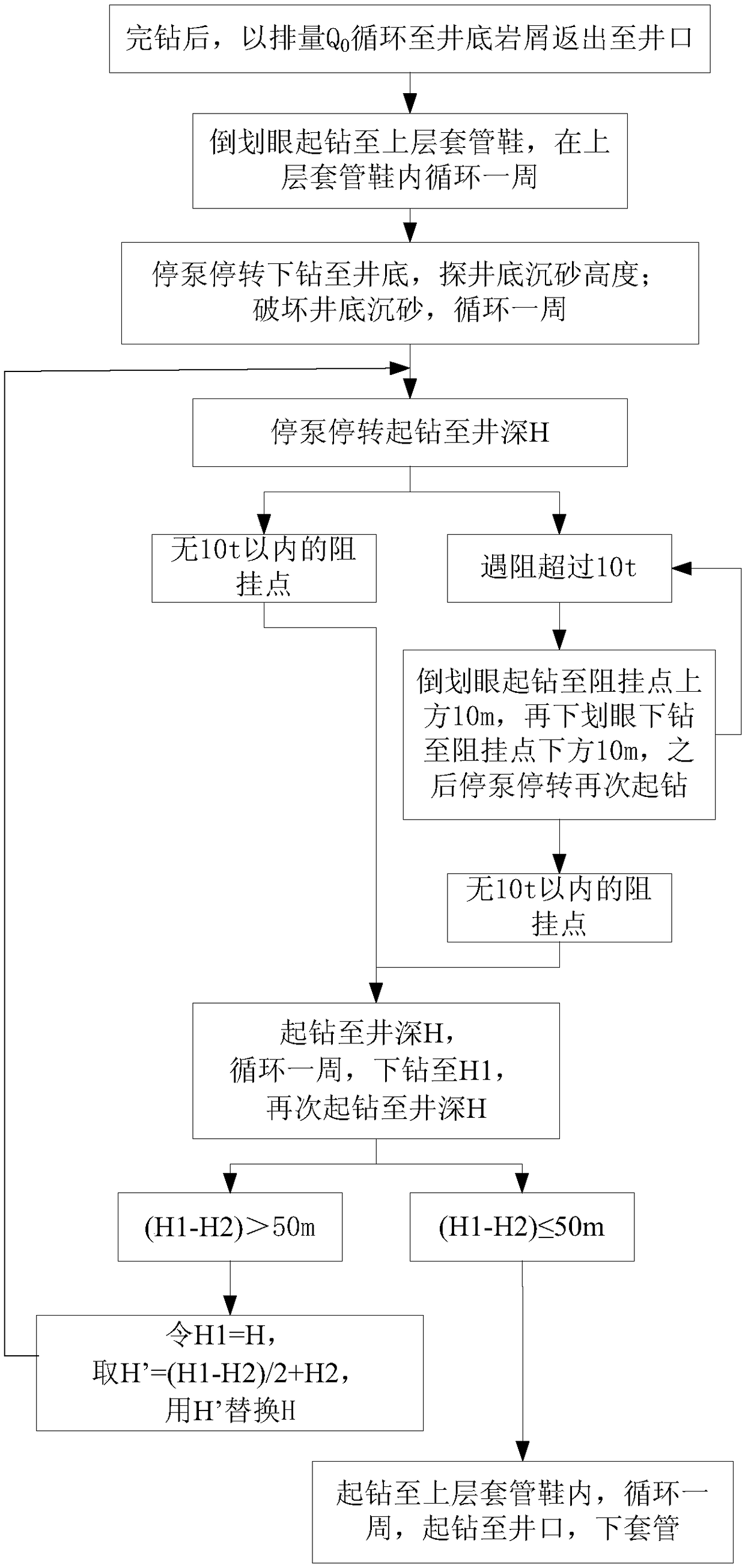
[0044] Such as figure 1 and figure 2 The drilling and completion methods in the shale reservoir in the shown drilling engineering, including the drilling process and the drilling completion process;

[0045] The drilling process includes:

[0046] (a) Use the PDC bit to drill to a vertical depth of 5-10m from the top of the shale reservoir according to the designed wellbore trajectory. During the drilling process, the viscosity of the drilling fluid is A, in centipoise; the density is B, in g / cm 3 ;Statistics The average drilling speed in the last 24 hours during the drilling process is X, the unit is m / h; the average speed of the drill pipe is Y, the unit is rpm; the average drilling pressure is Z, the unit is ton; the average displacement is Q, the unit is L / min Circulation, tripping out, changing the drill bit into a tricone bit equal to the PDC drill bit, and using a new screw drilling tool in the bottom hole assembly; (b) going down to the bottom of the well, explori...

Embodiment 2

[0052] Such as figure 1 and figure 2 The drilling and completion method in the shale reservoir in the shown drilling engineering, on the basis of Example 1, the displacement when replacing the heavy slurry and thick slurry in step (d) is Q', and the Q ' / Q=0.6~0.7; after the thick slurry is completely returned from the wellhead, increase the displacement to Q again. The displacement when replacing the slurry in step (b) is Q", said Q" / Q=1.2~1.4; after the slurry is completely returned from the wellhead, reduce the displacement to Q again. The slurry returns from the wellhead, and after the cuttings are screened out by the vibrating screen, it no longer enters the drilling fluid circulation pool. In step (b), when judging from the number of pump strokes that the slurry is coming out of the drill bit, the rotation speed of the drilling tool is increased; after the slurry returns from the wellhead, the rotation speed is adjusted to Y. Displacement Q 0 The annulus return veloc...


PUM


Abstract

The invention discloses a drilling and drilling completion method for the interior of a shale reservoir in drilling engineering. The method is characterized in that a low-viscosity drilling fluid is periodically fed in for a well in which the drilling speed is not obviously reduced after drilling is carried out in the shale reservoir, the occurrence possibility of a bit balling phenomenon is greatly decreased, and it is further ensured that the drilling pressure is effectively applied to a stratum; for a well in which the drilling speed is obviously reduced after drilling is carried out in theshale reservoir, the cleanness degree of the interior of a well shaft is greatly improved so that the increased drilling pressure can effectively act on the bottom of the well through a drill bit. According to the method, a high-cost drilling fluid system is not needed, and open-hole well sections of a shale bed section are fully trimmed and standardized only from the engineering aspect. The method solves the problems in the prior art that drilling is slowly conducted in the shale reservoir, the drilling speed is low, drill bits are difficult to pull out of or put into drilling holes after drilling, and the risk coefficients of lower casing pipes are high. The purposes of increasing the drilling speed in the shale reservoir, improving the engineering efficiency, reducing operation risks and increasing the safety coefficient of the lower casing pipes are achieved.

Description

technical field [0001] The invention relates to the field of drilling engineering, in particular to methods for drilling and completing drilling in shale reservoirs in drilling engineering. Background technique [0002] Shale gas refers to unconventional natural gas that occurs in organic-rich shale-dominated reservoir rock series. It is continuously generated biochemical gas, thermogenic gas or a mixture of both, and can exist in natural fractures in a free state. It exists in the surface of kerogen and clay particles in an adsorbed state, and a very small amount is stored in kerogen and asphaltene in a dissolved state. The proportion of free gas is generally 20% to 85%. Shale gas is natural gas extracted from shale formations. The main body is located in dark mud shale or high-carbon mud shale. Shale gas mainly exists in mudstone, high-carbon mudstone, shale and silt in an adsorbed or free state. Natural gas in sandy rock interlayers, which can be generated in various sta...

Claims


Application Information

Patent Timeline
Patent Type & Authority Applications(China)
IPC IPC(8): E21B10/50E21B21/00E21B7/00
CPCE21B7/00E21B10/50E21B21/00
Inventor 张远香
Owner 滦平县伟源矿业有限责任公司
Why Eureka
Eureka Blog
Learn More