
Automatic outage delay device

A power-off device and automatic technology, which is applied in the direction of engine components, machines/engines, mechanical equipment, etc., can solve problems such as a large increase in bearing wear, and achieve the effects of prolonging life, reducing wear, and reducing psychological burden

Inactive Publication Date: 2014-12-10
莫嘉林
View PDF10 Cites 0 Cited by
  • Summary
  • Abstract
  • Description
  • Claims
  • Application Information

AI Technical Summary

Problems solved by technology

Since the rotor bearings of the current exhaust gas turbocharger inevitably run under the condition of the above-mentioned no-oil supply state during engine operation, when the rotor of the exhaust gas turbocharger is running in inertia, the wear and tear of the bearings will be reduced. The amount of wear is greatly increased and is much greater than the amount of wear during effective operation

Method used


Image

  • Automatic outage delay device

Examples


Embodiment approach

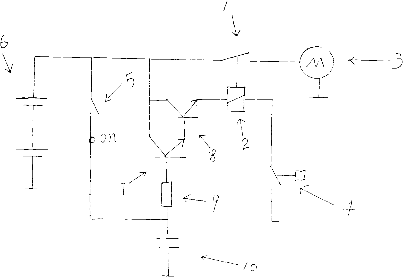
[0024] (1) The power supply circuit of the motor 3 is composed of the normally open contact 1 of the relay and the storage battery 6;

[0025] (2) The accumulator 6, the triode 8, the triode 7, the magnetic coil 2 and the oil pressure switch 4 are connected in series; The emitter, the circuit output end of the magnetic coil 2 is connected to the terminal of the oil pressure switch 4, the emitter of the triode 7 is connected to the base of the triode 8, and the base of the triode 7 is connected to the resistor 9.

[0026] (3) A delay circuit is composed of a resistor 9 and a capacitor 10; one end of the resistor is connected to the base of the triode 7, the other end of the resistor is connected to the on terminal of the key switch 5 and the positive pole of the capacitor 10, and the negative pole of the capacitor 10 is grounded.

[0027] Below in conjunction with accompanying drawing of description and specific embodiment, the present invention will be further described, and a...


PUM


Abstract

The invention relates to an automatic outage delay device. An engine oil supply system which is controlled by the automatic outage delay device is arranged in an exhaust turbocharged engine. The automatic outage delay device can automatically control a motor-driven oil pump to supply engine oil to the exhaust turbocharged engine before and after the engine is started, so that the condition that a rotor of the exhaust turbocharged engine runs without engine oil supply before and after the engine is started is eliminated, and the abrasion of a rotor bearing of the exhaust turbocharged engine is efficiently reduced, the operation of idling for minutes when the exhaust turbocharged engine is closed is no longer needed, the operation burden for operating the exhaust turbocharged engine is efficiently relieved, the fuel consumption is decreased and the exhaust emission is reduced.

Description

1. Technical field: [0001] The invention relates to an automatic delayed power-off device that can automatically power off the electric oil pump after the ignition switch of the engine is turned off for a period of time. The device can also automatically control the power on the electric oil pump before the engine starts, and Do not energize the electric oil pump while the engine is running. 2. Technical background: [0002] The current exhaust gas turbocharged engine needs a period of time from starting to the oil pump pumping the oil to the exhaust gas turbocharger. During this period, the rotor bearing of the exhaust gas turbocharger is in the state of no oil supply. operating in the state. [0003] When the exhaust gas turbocharged engine stops running, the rotor in the exhaust gas turbocharger does not stop rotating synchronously with the engine. Under the action of inertia, the rotor needs to undergo a process of natural deceleration from high-speed rotation until it ...

Claims


Application Information

Patent Timeline
Patent Type & Authority Patents(China)
IPC IPC(8): F01D25/18F02B39/14
Inventor 莫嘉林
Owner 莫嘉林
Learn More