An eccentric oscillating internal combustion engine with an optimized working mode
An eccentric swing, working mode technology, used in engine control, machine/engine, mechanical equipment, etc.
- Summary
- Abstract
- Description
- Claims
- Application Information
AI Technical Summary
Problems solved by technology
Method used
Image
Examples
Embodiment 3
[0088] Such as Figure 8 shown.
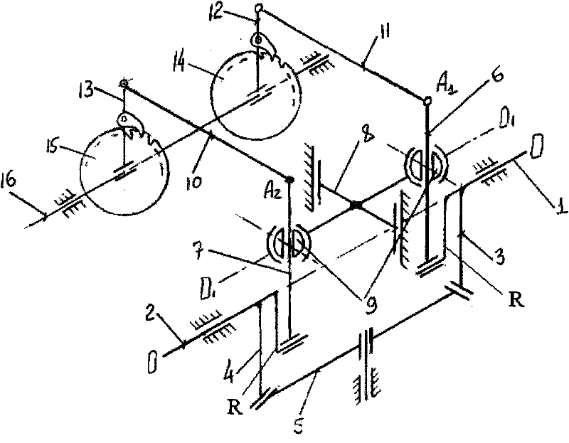
[0089] A transmission device for a four-stroke four-cylinder single-row internal combustion engine ( Figure 8 ) contains cylinders P1, P2, P3, P4 numbered according to their working order. The pulsating stepless speed regulating device is installed in the transmission device in the following manner; cylinders P4 and P2 are located on one side of the pulsating stepless speed regulating device, and cylinders P1 and P3 are located on the other side. The drive shaft 1 and 2 of the pulsating stepless speed regulating device are connected with the common connecting rod 3 and the swing crank 4, and the swing range of the crank 4' is α=90°.
[0090] In order to drive the flywheel 26 (without which the internal combustion engine cannot work), there is a crank rocker mechanism, which is connected to the input shaft 1, the transmission ratio of this mechanism is determined in the following way: when the rocker arm 27 swings from one extreme position t...
Embodiment 4
[0096] Such as Figure 9 shown.
[0097] The continuously variable transmission mechanism of the present embodiment has an output shaft 16 and four drive shafts (shafts 1, 2, 17 and 18), and the sequential working strokes of the eight cylinders are transmitted to an output shaft 16, in order to allow the slider 8 to be vertical at the same time To move, a slide block or a corner-type luffing mechanism can be respectively arranged on the left and right parts of the speed change mechanism (which can be realized by adopting the prior art).
[0098] The working process of the present embodiment is (as Figure 9 ): a row of cylinders (assuming this is P1, P2, P3 and P4 driving shafts 1 and 2 in the pulse transmission, which is as Figure 6 As described, the cylinders P5, P6, P7 and P8 form the second bank which drives the shafts 17 and 18 of the pulsator variator, just as what happens in the first bank, however, the second bank works in one stroke The phase shift within for the ...
Embodiment 5
[0100] Such as Figure 10 shown.
[0101] Figure 10 Shown is the structural form of a six-cylinder four-stroke internal combustion engine transmission mechanism arranged in a row. In this structural form, cylinders P1, P3, and P5 are located on one side of the pulse transmission mechanism to drive shaft 1, while cylinders P2, P4, and P6 are located on the The other side drive shaft 2 of the pulse type speed change mechanism. Valve shaft 20 and flywheel 26 are also driven as described for the four-cylinder one-row engine ( figure 2 ). Assuming that the swing angle α=120° of the rocker arm 4 can be realized.
[0102] The working characteristic of this six-cylinder engine is that the working cycle in each cylinder has four strokes and six cylinders. Therefore, in order to guarantee the continuity of the working strokes and to guarantee the most uniform work of the engine, it is recommended to carry out the so-called "empty" strokes.
[0103] Table 1 is explained below. E...
PUM
 Abstract
Description
Claims
Application Information
 - R&D
- Intellectual Property
- Life Sciences
- Materials
- Tech Scout
- Unparalleled Data Quality
- Higher Quality Content
- 60% Fewer Hallucinations
Browse by: Latest US Patents, China's latest patents, Technical Efficacy Thesaurus, Application Domain, Technology Topic, Popular Technical Reports.
© 2025 PatSnap. All rights reserved.Legal|Privacy policy|Modern Slavery Act Transparency Statement|Sitemap|About US| Contact US: help@patsnap.com


