Soft subdivision method of moire frange signal of grating
A Moiré fringe and grating technology, applied in the direction of using optical devices, measuring devices, instruments, etc., can solve the problems of residual DC level and DC level, high-order harmonics of signals, and inconsistency of two-channel signal amplitudes, so as to improve the accuracy and Resolution, simple hardware effects
Active Publication Date: 2010-08-25
CHONGQING UNIV OF TECH
View PDF5 Cites 13 Cited by
- Summary
- Abstract
- Description
- Claims
- Application Information
AI Technical Summary
Problems solved by technology
Due to the influence of the manufacturing process of the grating sensor, the lighting source, the grating gap, the grating diffraction, the characteristics of the photoelectric element, the power supply and the ambient temperature, the output signal of the photoelectric element contains high-order harmonics, residual DC level and DC level drift. , Inconsistent amplitude of two signals, poor phase orthogonality of two signals, etc. These factors directly affect the accuracy and reliability of various existing subdivision methods
Method used
View moreImage
Smart ImageViewing Examples
Examples
Embodiment Construction
Login to View More PUM
 Abstract
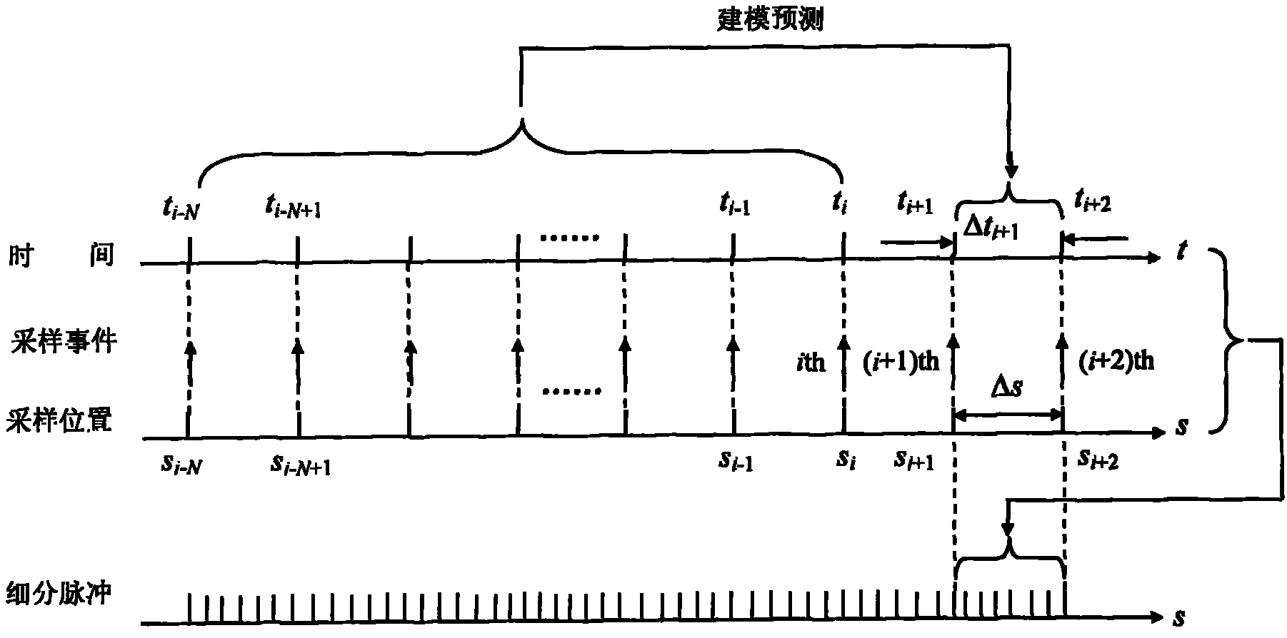
The invention provides a soft subdivision method of a moire frange signal of grating by adopting a micro-processing technology, which generally comprises the following steps of: transforming the information of space domain into time domain to process by using the space-time transformation technology; processing the data via software by using the theoretical modeling technology of time sequence to finish the accurate prediction of time capacity; then returning to the space domain by using the high-speed microprocessor technology and outputting the time pulse with spatial meaning to finish real-time subdivision of the moire frange signal of grating; and finally performing real-time correction on the subdivision error. The invention is applicable to high expansion subdivision of the moire frange signal of grating and improves the precision and resolution of the grating measurement system.
Description
technical field The invention relates to a new signal processing method of a precision displacement measuring sensor (including angular displacement and linear displacement). Background technique At present, grating technology is used in more than 90% of the field of precision displacement measurement. The measurement standard adopts periodic grating lines divided by space, and the displacement is obtained by counting the lines. Precision measurement requires the ability to measure straight lines of 1 μm to 0.1 μm and angles of 1″ to 0.1″. Such accuracy and resolution are difficult to achieve only by the precise engraving of the grating sensor itself. Therefore, it is necessary to subdivide the original Moiré fringe signal of the sensor, and use subdivision methods to improve the accuracy and resolution of the measurement system. The existing subdivision methods mainly include four categories: optical subdivision method, mechanical subdivision method, electronic subdivisio...
Claims
Login to View More Application Information
Patent Timeline
 IPC IPC(8): G01B11/25
Inventor 刘小康彭东林杨继森郑方燕
Owner CHONGQING UNIV OF TECH
Features
- R&D
- Intellectual Property
- Life Sciences
- Materials
- Tech Scout
- Unparalleled Data Quality
- Higher Quality Content
- 60% Fewer Hallucinations
Learn More Browse by: Latest US Patents, China's latest patents, Technical Efficacy Thesaurus, Application Domain, Technology Topic, Popular Technical Reports.
© 2025 PatSnap. All rights reserved.Legal|Privacy policy|Modern Slavery Act Transparency Statement|Sitemap|About US| Contact US: help@patsnap.com


