Pressure-compensated rotary joint

A rotary joint and pressure compensation technology, applied in the field of compensators, can solve problems such as unreliable sealing, and achieve the effects of avoiding leakage, compensating wear and eliminating stress

Active Publication Date: 2010-09-01
AEROSUN CORP
View PDF5 Cites 17 Cited by
  • Summary
  • Abstract
  • Description
  • Claims
  • Application Information

AI Technical Summary

Problems solved by technology

In order to solve the problem of unreliable sealing in the above-mentioned prior art, the Chinese patent application No. 200610041301.4 discloses a high-pressure resistant rotary compensator for pipelines with a new sealing structure, which includes a core tube, a sealing gland, Sealing seat, connecting pipe, one end of the core pipe is inserted into the connecting pipe, the connecting pipe is fixedly connected with one end of the sealing seat and fitted on the core pipe, the core pipe is provided with an annular outer boss, and the sealing seat is provided with an annular inner The boss, the sealing gland is set on the core tube and inserted into the other end of the sealing seat to resist the ring surface seal, the sealing gland and the sealing seat are connected through a connecting piece, and the feature is that there is formed between the sealing seat and the core tube a seal chamber in which the face seal is installed
However, this sealing structure only relies on the elastic sealing effect of the seal itself. When the medium pressure in the pipeline is too high and the seal is worn, it is still inevitable to leak.

Method used


Image

  • Pressure-compensated rotary joint
  • Pressure-compensated rotary joint

Examples


Embodiment 1

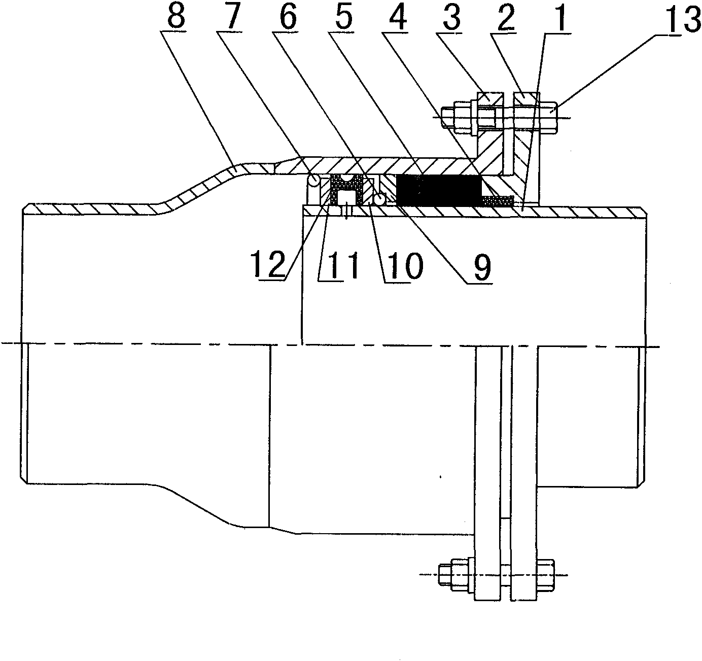
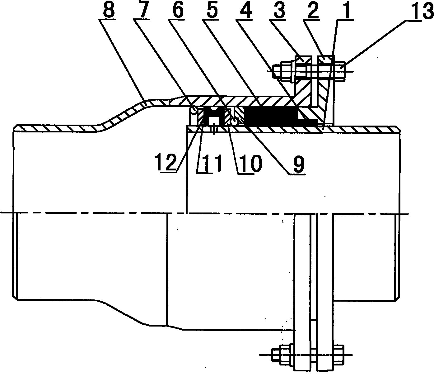
[0010] The pressure compensating rotary joint of this embodiment is as attached figure 1 As shown, it is mainly composed of an outer sleeve welded by a sleeve 3 and a reducer 8 , an inner tube 1 inserted into the sleeve 3 at one end, and a gland flange 2 sleeved outside the inner tube 1 . The sleeve 3 of the outer casing has an end flange, and the end flange is fixedly connected with the gland flange 2 through fastening bolts 13 . The thrust rings 7 and the connecting retaining rings 9 of circular sections distributed at intervals are fixedly installed in the inner hole of the insertion end of the sleeve 3 of the outer casing. The outer circumference of the insertion end of the inner tube 1 is fixed with a first retaining ring 11 and a second retaining ring 10 axially spaced apart, and there is a perforation on the pipe wall between the first retaining ring and the second retaining ring. The gland flange 2 has an extension ring extending into the outer casing sleeve 3 . The ...


PUM


Abstract

The invention relates to a pressure-compensated rotary joint, which belongs to the technical field of compensators. The rotary joint mainly comprises an outer sleeve, an inner tube and a gland flange, wherein a thrust ring and a connection baffle ring are fixed in the outer sleeve; a first baffle ring and a second baffle ring are fixed on the periphery of the inner tube, and the wall of the inner tube is provided with a through hole; the gland flange is provided with an extension ring; the end face of the first baffle ring is contacted with the thrust ring, and a rolling piece is installed between the end face of the second baffle ring and the opposite end face of the connection baffle ring; a seal ring is filled between the end face of the extension ring and the connection baffle ring, and a backing ring is installed in the extension ring; a sealing ring, of which the inner circle is provided with a groove, is installed between the first baffle ring and the second baffle ring; and the groove is communicated with the through hole in the wall of the inner tube. In the invention, a reliable double seal is formed by the seal ring and the sealing ring between the outer sleeve and the inner tube, and the abrasion of the sealing ring can be compensated, thereby effectively avoiding leakage at the movable joint of the pipeline for a long time.

Description

technical field [0001] The invention relates to a compensating rotary joint, in particular to a pressure compensating rotary joint, belonging to the technical field of compensators. Background technique [0002] As far as the applicant knows, the existing rotary compensator has the problem of unreliable sealing performance when transporting high-pressure medium. When the improved rotary compensator adopts double seals, when the large-diameter pipeline transports high-pressure medium, the internal pressure thrust caused by the medium pressure may cause excessive deformation of the sealing packing of the added sealing unit and cause failure. [0003] The search found that the Chinese patent application with the application number 02258709.8 discloses an improved rotary compensator, which includes an inner pipe and a special-shaped pipe joint. The inner pipe is equipped with a sealing seat and a gland flange connected by compression bolts. There is a boss on the inner pipe whe...

Claims


Application Information

Patent Timeline
Patent Type & Authority Applications(China)
IPC IPC(8): F16L27/08
Inventor 胡毅朱少华金南尚丽娟
Owner AEROSUN CORP
Why Eureka
Try Eureka