Method for automatically measuring special position of tunnel boring machine

A technology of automatic measurement and roadheading machine, which is applied in the directions of measuring device, angle measurement, surveying and navigation, etc., and can solve the problems of limiting the scope of application and not measuring the posture of the heading machine

Active Publication Date: 2010-09-01
TAIYUAN INST OF COAL SCI RES INST +1
View PDF1 Cites 50 Cited by
  • Summary
  • Abstract
  • Description
  • Claims
  • Application Information

AI Technical Summary

Problems solved by technology

[0005] The utility model patent with the publication number CN201013380 and the name of the fully automatic roadheader proposes to use an aerospace navigation locator to measure the position of the roadheader, but does not measure the posture of the roadheader; the publication number is CN101266134A and the name is the pose of the cantilever roadheader The invention patent of the measurement system and its method proposes to use a laser motorized total station to measure the coordinates of the excavation locomotive body in the geodetic coordinate system, the vehicle body yaw angle sensor to measure the vehicle body yaw angle, and the dual-axis inclination sensor to measure the vehicle body pitch angle and roll angle, the pitch angle and roll angle are based on the horizontal plane, but it is only applicable to the horizontal excavation roadway. In addition, this method requires the installation position of the total station to be horizontal to the excavation body, which further limits the method scope of application

Method used


Image

  • Method for automatically measuring special position of tunnel boring machine
  • Method for automatically measuring special position of tunnel boring machine
  • Method for automatically measuring special position of tunnel boring machine

Examples


Embodiment Construction

[0137] The present invention will be further described below in conjunction with accompanying drawing:

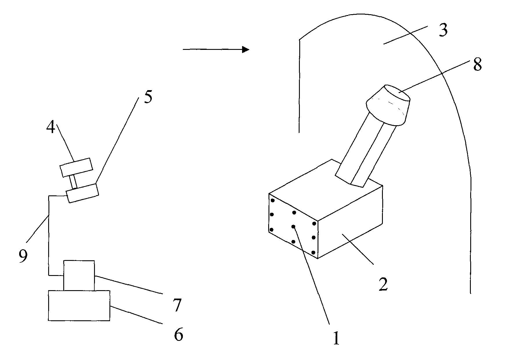
[0138] figure 1 Shown is the location map of measuring instruments, roadheaders, and coal and rock sections. The location, coverage angle, direction, and height of each part must be reasonable and correct, and the wires of each instrument must be firmly connected.

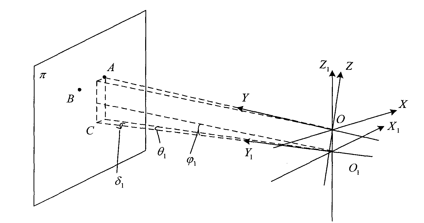
[0139] figure 2 Shown is the industrial camera, laser pointing device, datum plane, and datum point positions. It can be seen from the figure that the π plane is the datum plane, and points A and B are the datum points.

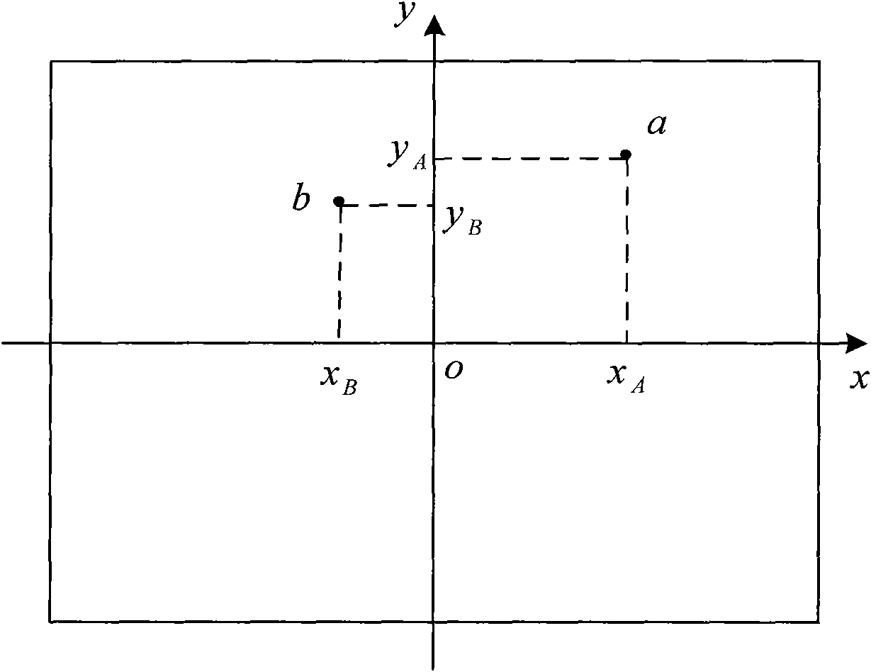
[0140] image 3 Shown is a schematic diagram of the measurement plane, and the measurement planes are all on the X, Y, and O coordinate axes.

[0141] Figure 4 As shown, it is the principle diagram of space pose calculation. It can be seen in the figure that the required roadway orientation is determined by the beam of the laser pointing device, and the world coordinate system OXYZ is est...


PUM


Abstract

The invention relates to a method for automatically measuring the special position of a tunnel boring machine. According to the practical situation of the tunneling operation of the tunnel boring machine in a small underground space of a coal mine, an industrial view camera, an industrial computer, a laser orientation instrument and an image acquisition card are arranged on the back part of the tunnel boring machine. The position of the tunnel boring machine on a coal petrography cross section is measured and calculated, the most reasonable position of a machine body is determined, a command on an excavating operation is made and operators are far away from hazardous areas so as to reduce sudden accidents, enhance excavating safety and keep the tunnel boring machine on a best and most reasonable position and in a best and most reasonable state. A maximum cover angle is + / -60 degrees, a displacement detection deviation is less than 10 millimeters, the detection accuracy of a deflection angle is + / -12 gon, the detection accuracy of a pitch angle is + / -6 gon and the detection accuracy of a roll angle is + / -6 gon so as to improve excavating quality and efficiency. The method is advanced, reasonable and correct, is a very ideal method for measuring the excavation position of a coal extraction tunnel boring machine and can be used in tunnel excavation operation.

Description

technical field [0001] The invention relates to a method for automatically measuring the spatial position and posture of a roadheader, belonging to the technical field of coal mine mining equipment application, detection and measurement. Background technique [0002] The cantilever roadheader is the most important mining equipment in large and medium-sized coal mines. [0003] The coal mining roadheader works reciprocally in a narrow roadway. The space is limited, the environment is harsh, the working flour and dust are large, and the light on the job site is poor. Especially when cutting the roadway floor, the operator's line of sight is blocked by the machine body. It is difficult to judge the cutting position and posture of the roadheader, which brings great difficulties to the control of the direction of the excavation, resulting in slow excavation speed, low production efficiency, serious over-exploitation and under-exploitation of the roadway, poor excavation quality, ...

Claims


Application Information

Patent Timeline
Patent Type & Authority Applications(China)
IPC IPC(8): G01C1/00
Inventor 田原王德光金江于向东张忠国张胜达侯林冯家鹏
Owner TAIYUAN INST OF COAL SCI RES INST
Why Eureka
Try Eureka