Ultrasonic bending fatigue experimental device

A technology of bending fatigue and experimental equipment, applied in the fields of durability testing and fatigue of structural materials, which can solve problems such as converting to transverse waves

Inactive Publication Date: 2010-09-01
NANTONG JINNIU MACHINERY MFR +1
View PDF4 Cites 24 Cited by
  • Summary
  • Abstract
  • Description
  • Claims
  • Application Information

AI Technical Summary

Problems solved by technology

Since the existing ultrasonic fatigue test device does not have an experimental device that can convert the longitudinal wave into a transverse wave, at the same time, because in the existing axially loaded ultrasonic fatigue test device, the dynamic load preload and static load of the tension and compress

Method used


Image

  • Ultrasonic bending fatigue experimental device
  • Ultrasonic bending fatigue experimental device
  • Ultrasonic bending fatigue experimental device

Examples


Embodiment Construction

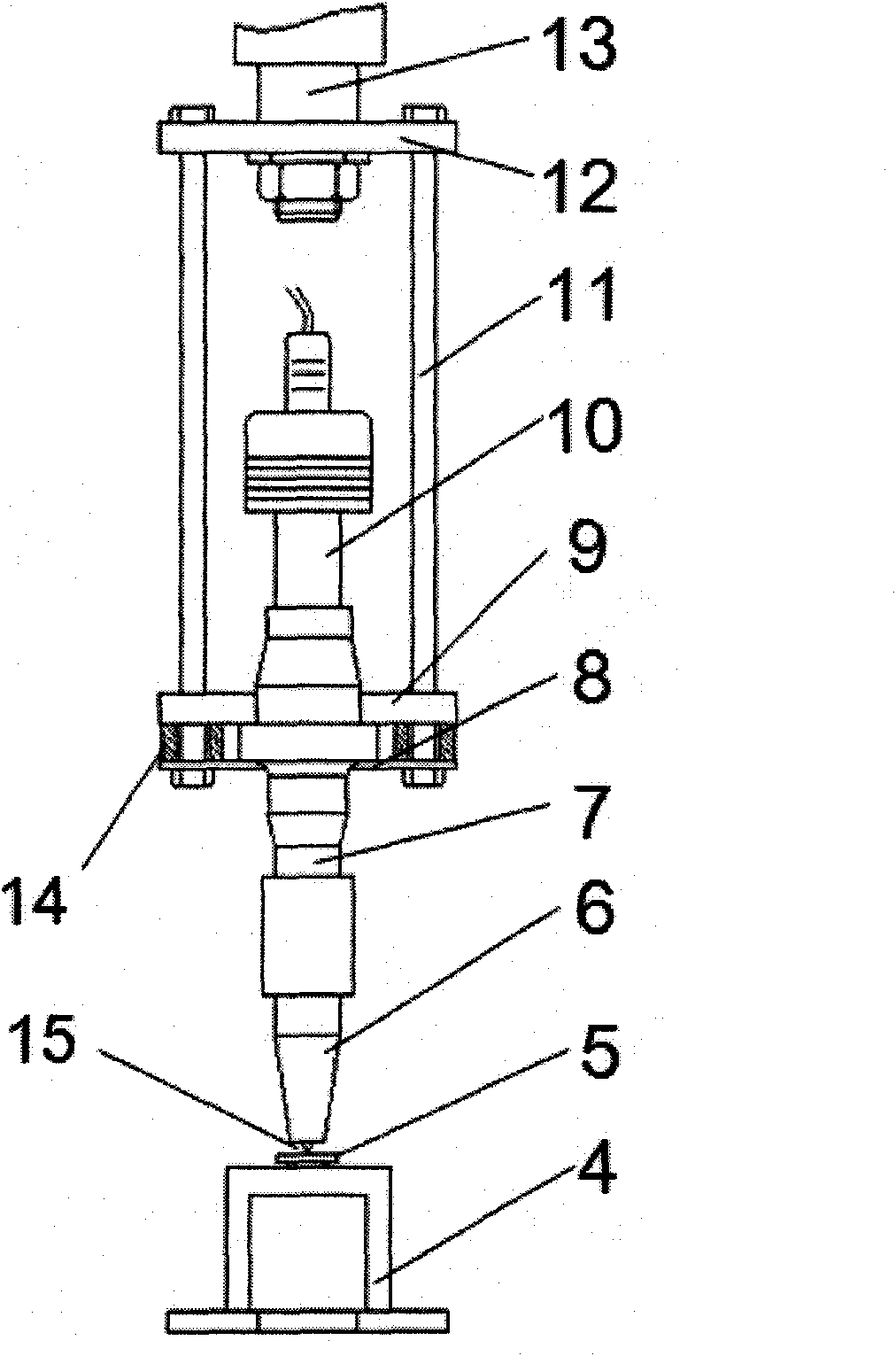
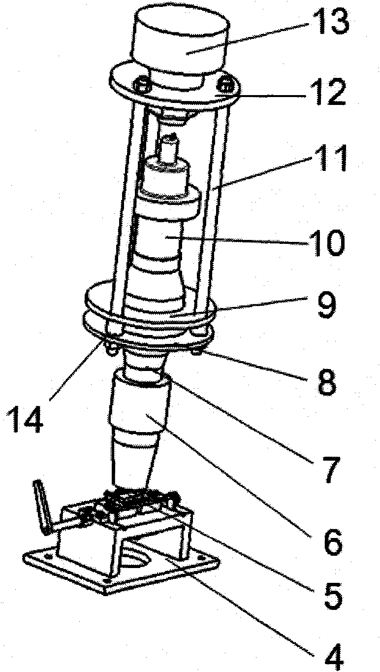
[0051] This embodiment is an ultrasonic bending fatigue test device, which is used for a three-point bending fatigue test of metal materials at a frequency of 20 kHz, and can complete a bending fatigue test with a stress ratio R>0. According to the design of the connector and the low-magnification displacement amplifier in the ultrasonic bending fatigue test device, the stress amplitude loading range of the bending fatigue specimen is between 250-850 MPa. The ultrasonic bending fatigue specimen must meet the bending resonance condition of 20kHz, and the minimum length of the bending fatigue specimen should be greater than 30mm.

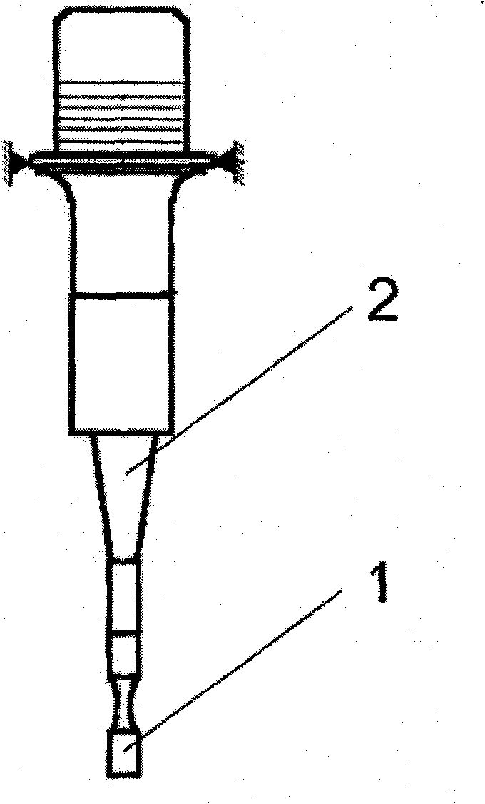
[0052] The ultrasonic bending fatigue test device includes a supporting device 4 , a bending fatigue sample 5 , a low-magnification displacement amplifier 6 , a connector 7 , a transducer 10 , a force transmitter, a static load adding device 13 , an isolation block 14 and an indenter 15 . The power transmission device is a frame structure composed of ...


PUM


Abstract

The invention relates to an ultrasonic bending fatigue experimental device, wherein a transducer is positioned in a force transmitter and connected with a connector. The transducer is positioned in the middle of the ultrasonic bending fatigue experimental device; a backing plate and an upper connecting plate as well as a lower connecting plate of the force transmitter are fixedly connected through force transmitting rods. One end of the connector penetrates through the lower connecting plate at the lower end of the force transmitter and is connected with a displacement amplifier, and the other end penetrates through the upper connecting plate and is connected with the transducer. A supporting device is positioned below the displacement amplifier; and a static load force applying device penetrates through the central hole of the backing plate and is fixedly connected with the backing plate. The transducer, the connector, the displacement amplifier and a pressure head form a longitudinal resonance system, and a longitudinal vibration load is transferred to a bending fatigue sample through the pressure head, so that bending vibration is generated by the bending fatigue sample. The position of the supporting point of the bending fatigue sample can be automatically regulated through a positioning guide screw to realize an ultrasonic bending fatigue experiment, the ultrasonic bending fatigue experiments of the samples with different loading loads and different geometrical sizes can be realized, and the ultrasonic bending fatigue experimental device is suitable for carrying out the bending fatigue experiment by utilizing an axial loading ultrasonic fatigue experiment machine.

Description

technical field [0001] The invention relates to the fields of structural material fatigue and durability testing, in particular to an ultrasonic bending fatigue test device. Background technique [0002] Fatigue failure is the main failure mode of structural parts under alternating loads, such as crankshafts, gears, connecting rods, springs, bolts and other components, as well as pressure vessels, vehicles, aircraft, offshore platforms, welded steel bridges and other structures. fatigue damage. The failure accidents of engineering components caused by fatigue damage account for 80% of the total accidents. Because fatigue fracture occurs suddenly and leads to catastrophic accidents, the fatigue failure of materials has always been a subject of research and concern by scholars and engineering circles at home and abroad. [0003] In aerospace, automobile, railway, nuclear industry, machinery and other industrial fields, some structural components are subjected to high-frequen...

Claims


Application Information

Patent Timeline
IPC IPC(8): G01N3/20G01H9/00
Inventor 薛红前
Owner NANTONG JINNIU MACHINERY MFR
Why Eureka
Try Eureka