Three-station vacuum arc extinguish chamber for isolated grounding

A vacuum interrupter, isolation and grounding technology, applied in the direction of high-voltage air circuit breakers, electrical components, electrical switches, etc., can solve the disadvantages of vacuum interrupter, increase the complexity of materials, components and tests, and increase the size of switchgear components and other problems, to achieve the effect of simple structure, low cost, and improved insulation reliability

Inactive Publication Date: 2010-09-01
山东晨鸿电气有限公司 +2
View PDF7 Cites 18 Cited by
  • Summary
  • Abstract
  • Description
  • Claims
  • Application Information

AI Technical Summary

Problems solved by technology

Two pairs of moving and static contacts usually need two sets of operating mechanisms to cooperate with them. The corresponding operating mechanisms can use spring operating mechanisms or electric operating mechanisms. In this case, the three-station vacuum interrupter increases The complexity of materials, components and testing increases, and the size of switchgear components increases accordingly, which is very unfavorable for vacuum interrupters

Method used


Image

  • Three-station vacuum arc extinguish chamber for isolated grounding
  • Three-station vacuum arc extinguish chamber for isolated grounding
  • Three-station vacuum arc extinguish chamber for isolated grounding

Examples


Embodiment Construction

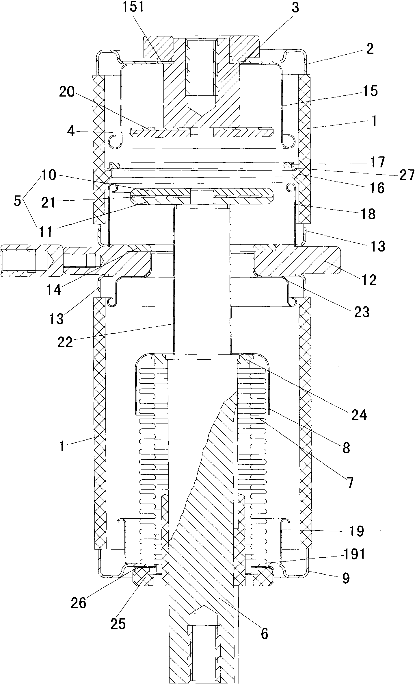
[0022] see figure 2 The schematic diagram of the structure of the closed state of the three-station vacuum interrupter for isolation and grounding of the present invention is shown, including an insulating shell 1, a static cover plate 2, a static end conductive rod 3, a static contact 4, a moving contact 5, and a moving end conductive rod. Rod 6, bellows 7, bellows protective cover 8, moving cover 9, static ground contact 14, static end isolation shield 15, intermediate isolation shield 17, ground isolation shield 18 and moving end equalizing cover 19. The moving contact 5 is welded by the moving isolating contact 10, the second copper sheet 21 and the moving grounding contact 11, the static contact 4 and the moving isolating contact 10 are made of copper-tungsten alloy, the static grounding contact 14 and the moving The ground contact 11 is made of copper chromium alloy.

[0023] The static cover plate 2 and the movable cover plate 9 are respectively arranged at the upper ...


PUM


Abstract

The invention relates to a three-station vacuum arc extinguish chamber for isolated grounding, which is mainly applied to medium-voltage power switch equipment and comprises an isolated outer shell, a fixed cover plate, a movable cover plate, a fixed end conducting rod, a movable end conducting rod, a fixed contact, a movable contact, a corrugated pipe and a protective cover, wherein the fixed cover plate and the movable cover plate are respectively arranged at the upper end and the lower end of the isolated outer shell, the top of the fixed end conducting rod is welded with the fixed cover plate, and the bottom of the fixed end conducting rod is welded with the fixed contact; the protective cover of the corrugated pipe is arranged outside the corrugated pipe; the movable contact is formed by welding an isolated contact and a movable grounding contact; the middle of the isolated outer shell is provided with a grounding ring, the upper surface and the lower surface of the grounding ring are connected with the isolated outer shell through a sealing ring, and the upper surface of the grounding ring is welded with a fixed grounding contact; the bottom of the fixed cover plate is welded with a fixed end isolated shielding cover, a middle isolated shielding cover is arranged on a bead at the upper part of an inner cavity of the isolated outer shell, and a grounding isolated shielding cover is arranged on the grounding ring; one end of the movable end conducting rod is welded with the movable grounding contact after penetrating through the cover plates, the corrugated pipe, the grounding isolated shielding cover, the middle isolated shielding cover and the fixed end isolated shielding cover, and a movable end voltage-sharing cover is welded on the movable cover plate. The invention has the advantages of simple structure and low cost.

Description

technical field [0001] The invention relates to a vacuum interrupter, in particular to a three-station vacuum interrupter for isolation and grounding. Background technique [0002] The existing two-station vacuum interrupter can only realize closing and isolation functions, such as figure 1 The structure diagram of the existing two-station vacuum interrupter is shown, including the insulating shell 1', the static cover plate 2', the static end conductive rod 3', the static contact 4', the shielding cover 5', and the moving contact 6' , moving end conductive rod 7', bellows 8', bellows protective cover 9' and moving cover 10', static cover 2' and moving cover 10' are respectively located at the upper and lower ends of the insulating shell 1', shielding cover 5 'Set in the inner cavity of the insulating shell 1', the static contact 4', part of the static end conductive rod 3', the moving contact 6', part of the moving end conductive rod 7' and the bellows protective cover 9' ...

Claims


Application Information

Patent Timeline
Patent Type & Authority Applications(China)
IPC IPC(8): H01H33/664
Inventor 谢国良冉隆科刘永飞刘箭飞杨冬梅黄志军刘志远孔国威
Owner 山东晨鸿电气有限公司
Why Eureka
Try Eureka