Electronic switch

An electronic switch and circuit technology, applied in the direction of circuits, relays, electrical components, etc., can solve the problems of difficulty in popularization and high cost, and achieve the effects of reliable control, low circuit cost and ingenious conception

Inactive Publication Date: 2010-09-01
施耐德(重庆)电工有限公司
View PDF2 Cites 11 Cited by
  • Summary
  • Abstract
  • Description
  • Claims
  • Application Information

AI Technical Summary

Problems solved by technology

Although this method can effectively suppress arc generation and prolong the service life of relay contacts, it is expensive and difficult to popularize

Method used


Image

  • Electronic switch
  • Electronic switch
  • Electronic switch

Examples


Embodiment Construction

[0040] In order to facilitate the understanding of those skilled in the art, the present invention will be described in further detail below in conjunction with the accompanying drawings:

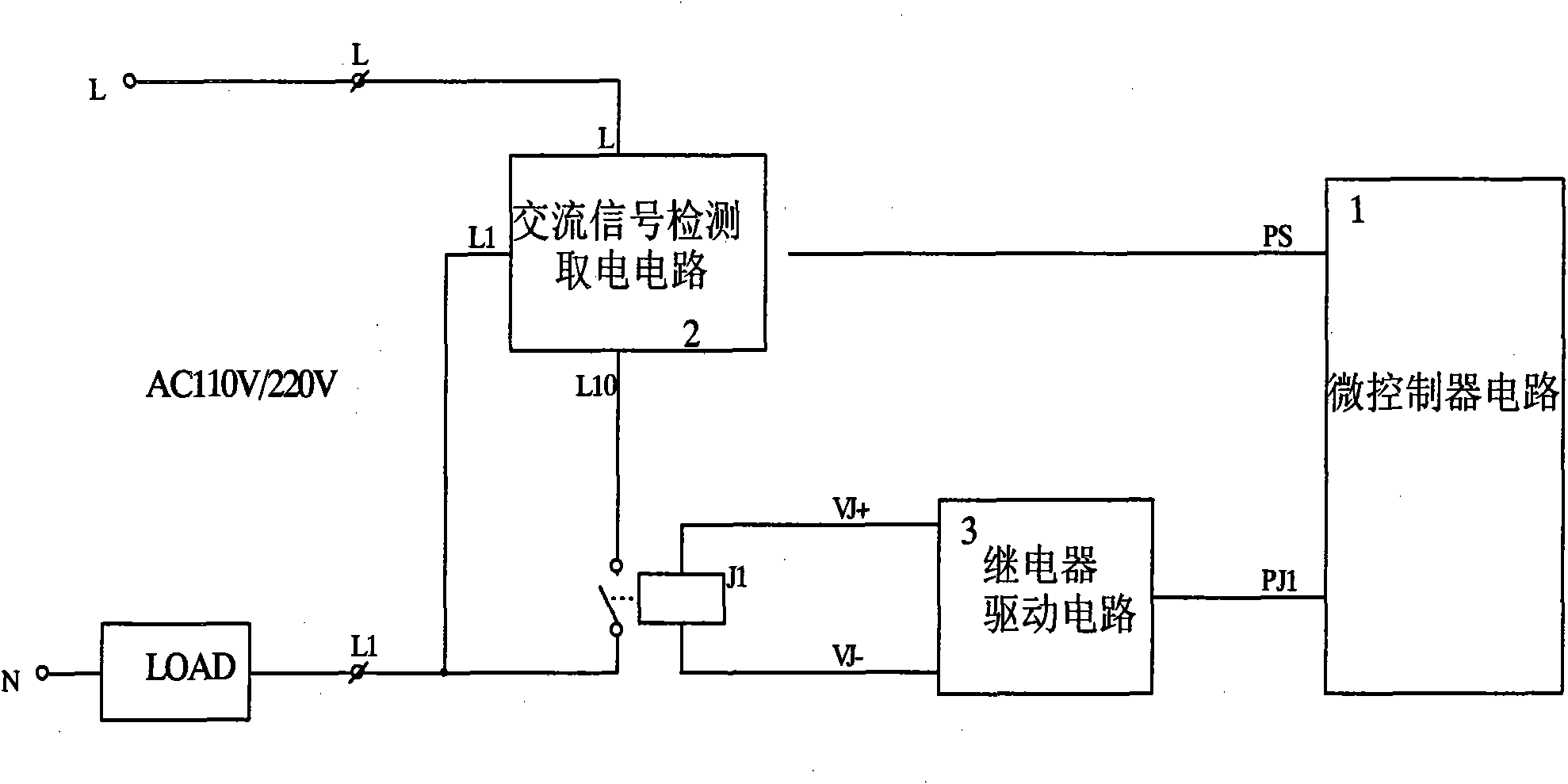
[0041] Such as figure 1 It is a schematic block diagram of the basic principles of the electronic switch in the present invention. The electronic switch includes a relay J1 connected to the load, a relay drive circuit 3, a microcontroller circuit 1, and an AC signal detection power-taking circuit 2; the input terminal of the AC signal detection power-taking circuit 2 is connected to the contact of the relay J1, The output end is connected with the input end of the microcontroller circuit 1; the output end of the microcontroller circuit 1 is connected with the relay driving circuit 3.

[0042] Several examples are given below to describe in detail.

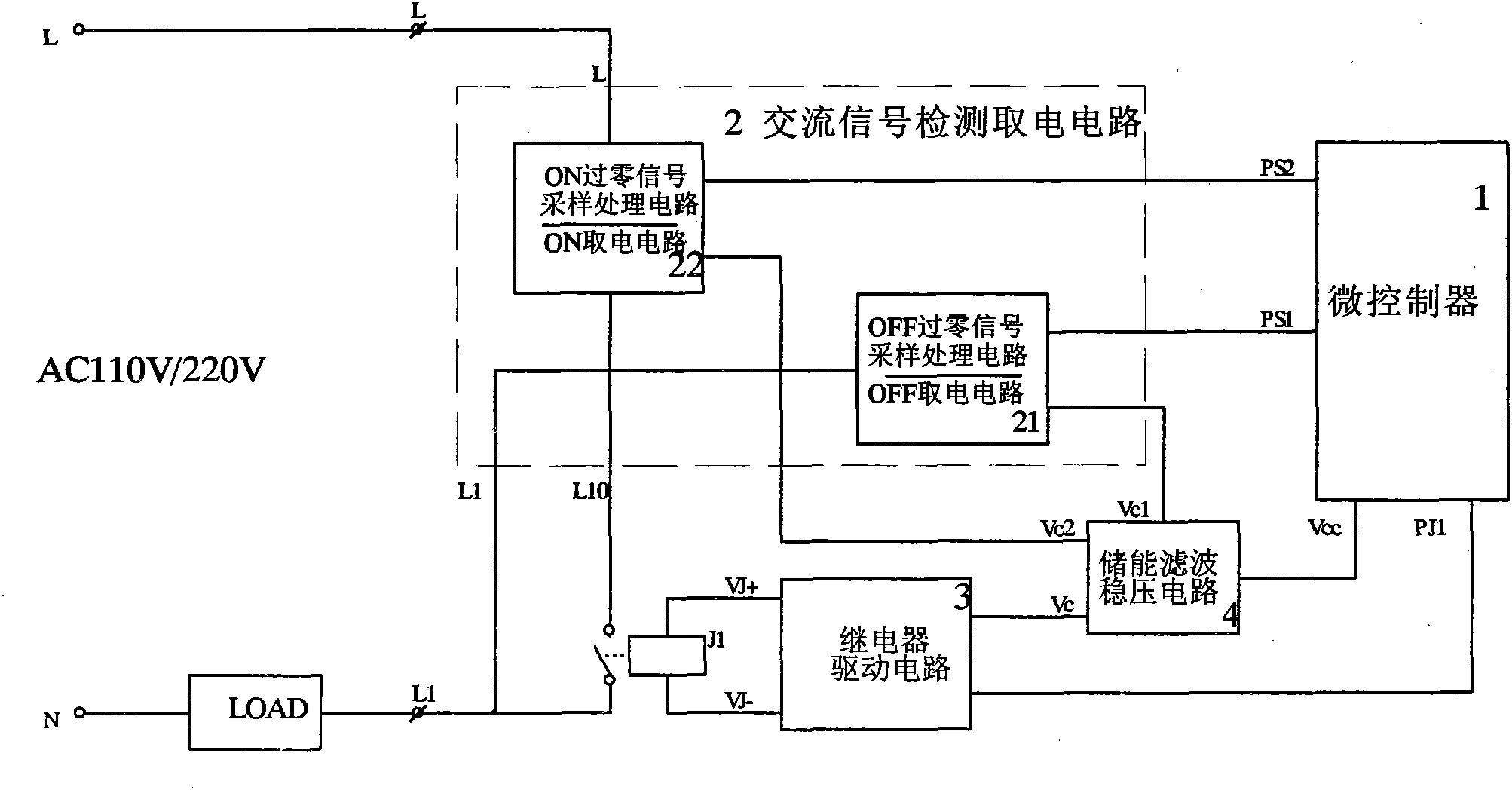
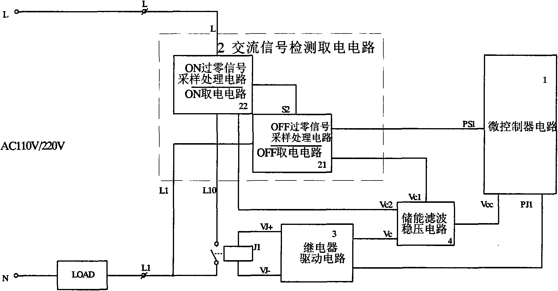
[0043] Such as figure 2 shown. The AC signal detection and power-taking circuit 2 includes an OFF zero-crossing signal sampling processing...


PUM


Abstract

The invention relates to an electronic switch for alternating current passing-zero switching. The electronic switch comprises a relay connected with a load, a relay drive circuit, a microcontroller circuit and an alternating current signal detection power circuit, wherein the input end of the alternating current signal detection power circuit is connected with a contact of the relay, while the output end is connected with the input end of the microcontroller circuit; the output end of the microcontroller circuit is connected with the relay drive circuit; and the alternating current signal detection power circuit comprises an OFF signal sample processing circuit, an ON signal sample processing circuit and a signal processing circuit. In the invention, the microcontroller is adopted to control the relay contact to switch at the passing-zero moment of an alternating current power supply, so the problem that an electronic switching relay is damaged by the electric arc and surge impact which are generated instantly at the on or off moment of the contact is solved, the load capability and the service life of the relay contact are obviously improved, and the switch performance is higher and safer; and the circuit is low in cost and easy to implement.

Description

technical field [0001] The invention relates to an electronic switch, in particular to an electronic switch capable of switching when an AC voltage signal crosses zero. Background technique [0002] In various known electronic switches, silicon controlled rectifiers or relays are mainly used as terminal switching devices to drive loads on and off. The on-off control of the relay in the electronic switch with the relay as the terminal switching device is often random, so that when the relay contacts are closed and disconnected, surge currents and arcs will be generated, which greatly shortens the life of the relay contacts. [0003] In order to solve the above problems, in the prior art, silicon controlled rectifiers or field effect transistors are often connected in parallel at both ends of the relay contacts. When the switch needs to be turned on, first control the silicon controlled rectifier or field effect tube to conduct, and then control the relay contact to close; wh...

Claims


Application Information

Patent Timeline
Patent Type & Authority Applications(China)
IPC IPC(8): H01H47/00
Inventor 熊大勇廖智鑫金德奎
Owner 施耐德(重庆)电工有限公司
Why Eureka
Try Eureka