
Sensor signal amplifying and conditioning circuit

A technology for amplifying and conditioning circuits and sensor signals, applied in differential amplifiers, DC-coupled DC amplifiers, etc., can solve the problems that the temperature coefficient cannot have good consistency, and the gain cannot be adjusted flexibly, so as to achieve low cost and expand the scope of application Effect

Inactive Publication Date: 2010-09-01
无锡伯顿电子科技有限公司
View PDF5 Cites 21 Cited by
  • Summary
  • Abstract
  • Description
  • Claims
  • Application Information

AI Technical Summary

Problems solved by technology

However, the gain resistor of the existing instrumentation amplifier is either set internally as a fixed value, and the gain cannot be adjusted flexibly, which has great limitations; difference, its temperature coefficient cannot have good consistency
Moreover, although the existing instrumentation amplifier has a reference voltage input terminal to realize the zero point adjustment function, it cannot be directly realized by a simple circuit in the form of an external resistor divider.

Method used


Image

  • Sensor signal amplifying and conditioning circuit
  • Sensor signal amplifying and conditioning circuit
  • Sensor signal amplifying and conditioning circuit

Examples


Embodiment Construction

[0013] The specific embodiments of the present invention will be further described below in conjunction with the accompanying drawings.

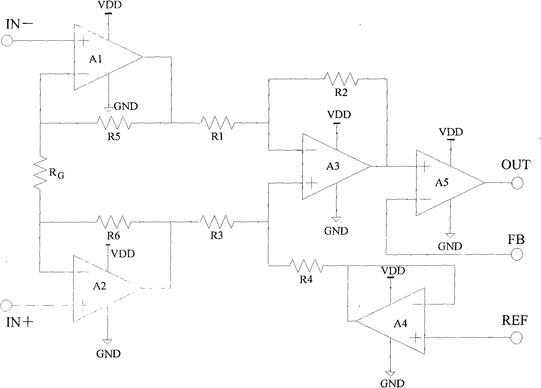
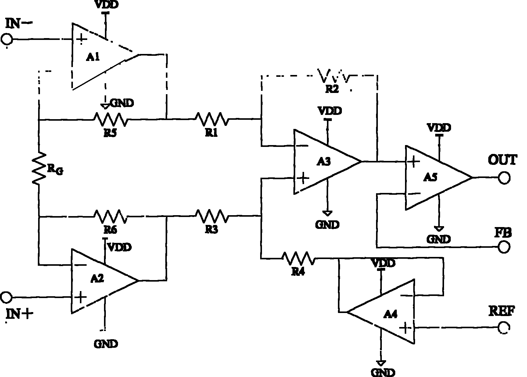
[0014] Such as figure 1 As shown, the present invention is made up of two-stage amplifying units, wherein the first-stage amplifying unit is an instrument amplifier, and in this embodiment, the instrument amplifier is a three-op-amp instrument amplifier, which consists of the first op-amp A1, the second op A2, the third operational amplifier A3, the first resistor R1, the second resistor R2, the third resistor R3, the fourth resistor R4, the fifth resistor R5, the sixth resistor R6 and the gain resistor R G constitute.

[0015] See figure 1 , wherein the non-inverting input terminal of the first operational amplifier A1 and the non-inverting input terminal of the second operational amplifier A2 are respectively used as the first differential signal input terminal IN- and the second differential signal input terminal IN+ of the present inve...


PUM


Abstract

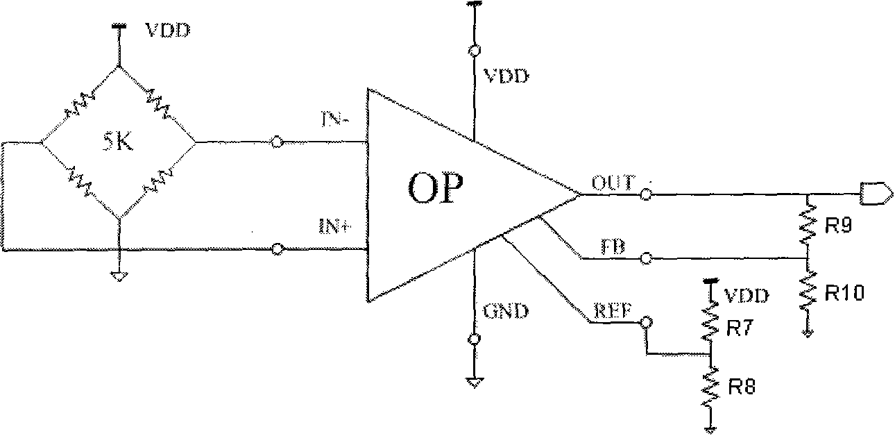
The invention relates to a sensor signal amplifying and conditioning circuit which comprises an instrument amplifier, a same-phase scale amplifier and a voltage follower, wherein the input end of the instrument amplifier is connected with a differential input signal; the voltage follower inputs the reference voltage into the reference voltage end of the instrument amplifier; the output signal of the instrument amplifier is accessed to the same-phase input end of the same-phase scale amplifier; the reverse-phase input end of the same-phase scale amplifier is used as a gain adjusting end; and the output end of the same-phase scale amplifier is used as the output end of the whole sensor signal amplifying and conditioning circuit. The invention is used for amplifying the small differential signal sent by the sensor and converting the differential signal into the single-end signal output to the reference end. By arranging the external resistor, the invention can realize zero-point and gain adjustment, extend the application range, and complete the impedance matching through the voltage follower.

Description

technical field [0001] The invention relates to the field of integrated circuits, in particular to an integrated sensor signal amplification and conditioning circuit. Background technique [0002] The output signal of the sensor is generally relatively weak, and it needs to be amplified, filtered, and level adjusted by the front circuit to meet the requirements of the single-chip microcomputer for the input signal. Because instrumentation amplifiers can amplify very weak differential voltage signals and have high input impedance, they are widely used in strain gauge bridge interfaces for measuring pressure and temperature, thermocouple temperature detection, and various low-side and high-side currents checking. However, the gain resistor of the existing instrumentation amplifier is either set internally as a fixed value, and the gain cannot be adjusted flexibly, which has great limitations; difference, its temperature coefficient cannot have good consistency. Moreover, al...

Claims


Application Information

Patent Timeline
Patent Type & Authority Applications(China)
IPC IPC(8): H03F3/45
Inventor 周敬训王智郑金荣常军沈蓉蓉
Owner 无锡伯顿电子科技有限公司
Learn More