Image display
A technology of image display and display panel, applied in static indicators, instruments, nonlinear optics, etc., can solve problems such as inability to compensate brightness, and achieve the effect of reducing power consumption
- Summary
- Abstract
- Description
- Claims
- Application Information
AI Technical Summary
Problems solved by technology
Method used
Image
Examples
example 1
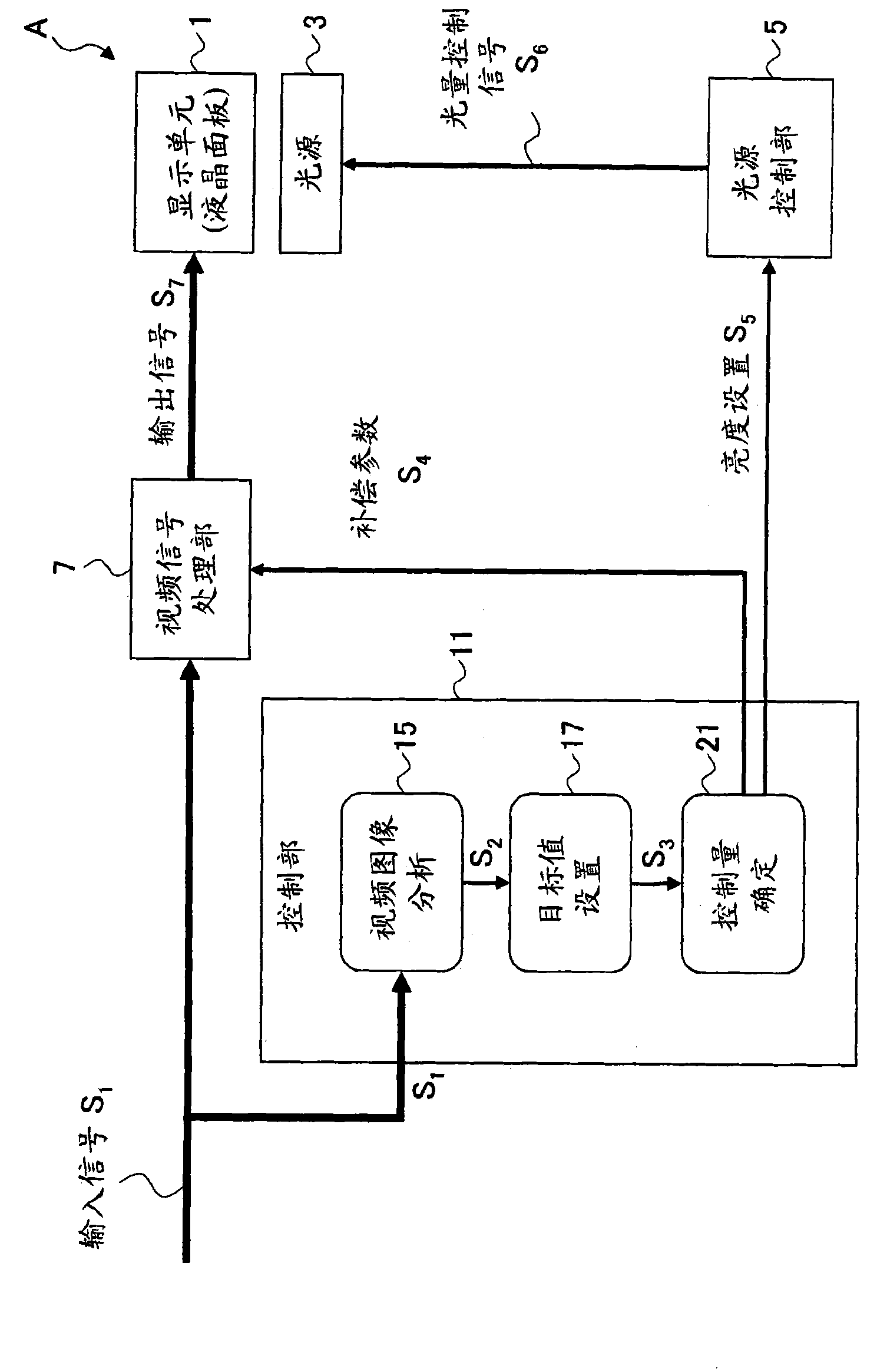
[0080] Figure 14 is a diagram showing an example of applying the above image display technology to a mobile phone, and is a functional block diagram showing one configuration example of a mobile phone with a One-Seg audiovisual function. Such as Figure 14 As shown, the mobile phone B according to this example includes a display unit 31, a light source 33, a light source control section 35, a video signal processing section 37, an antenna 40, a control section 41 for controlling the entire mobile phone, a radio control section 43, a received data processing section 45 . A video signal generation unit 47 , and an input unit 51 . This configuration is the same as a general mobile phone with One-Seg reception function. However, the input signal from the video signal generating section 47 is input to both the video signal processing section 37 and the control section 41 , and the compensation setting and the input signal output from the control section are input to the video sign...
example 2
[0082] Figure 15 is shown using Figure 14 A view showing an example of a mobile phone. As shown in the diagram on the left, the present example is configured to focus on the fact that power fluctuations, attributable to the Dynamic control of the light sources in the display unit 31 . Since the occurrence of such disturbances is not preferred, as shown in the diagram on the right, a dynamic control of turning off the display unit 31 after detection of an outgoing / incoming communication 55 is provided, i.e. an image-based display technique according to this embodiment function of the control. Unlike the case of watching television, the display in radio communication is based on e-mail, Internet, etc., for example. This type of display does not require as much dynamic control as the display in television reception and the reception of recorded TV programs. Therefore, in this example, a function of turning off the dynamic control function when the necessity of dynamic cont...
example 3
[0084] Next, refer to Figure 16 , an example in which this image display technology is applied to a display unit using an OLED (Organic Light Emitting Diode) as a light source will be described. Figure 16 The shown display unit is a liquid crystal display unit using an OLED as a light source. Basically, this display unit can be used as a display portion of a mobile terminal. In the case of using an OLED as a light source, its lifetime is a problem, and reducing luminance is effective in prolonging the lifetime of the OLED.
[0085] If energy-saving control is performed on the light source of the OLED in the above-described manner, the service life of the light source can be extended. For example, if the peak brightness of the light source of an OLED is reduced by 10%, the reliability cycle of the display panel can be increased by 10%. Of course, this technique is particularly effective in the case of OLEDs, although LEDs or the like can alternatively be used for the light...
PUM
 Abstract
Description
Claims
Application Information
 - R&D
- Intellectual Property
- Life Sciences
- Materials
- Tech Scout
- Unparalleled Data Quality
- Higher Quality Content
- 60% Fewer Hallucinations
Browse by: Latest US Patents, China's latest patents, Technical Efficacy Thesaurus, Application Domain, Technology Topic, Popular Technical Reports.
© 2025 PatSnap. All rights reserved.Legal|Privacy policy|Modern Slavery Act Transparency Statement|Sitemap|About US| Contact US: help@patsnap.com


