Safety brake of elevator tractor

A technology of elevator traction machine and safety brake, which is applied in the direction of hoisting device, etc., to achieve the effect of low energy consumption, low working voltage, vibration and noise reduction

Active Publication Date: 2010-09-08
成都瑞迪智驱科技股份有限公司
View PDF6 Cites 10 Cited by
  • Summary
  • Abstract
  • Description
  • Claims
  • Application Information

AI Technical Summary

Problems solved by technology

[0005] The purpose of the present invention is to provide a high-braking performance, low-cost and low-noise elevator traction machine

Method used


Image

  • Safety brake of elevator tractor
  • Safety brake of elevator tractor
  • Safety brake of elevator tractor

Examples


Embodiment Construction

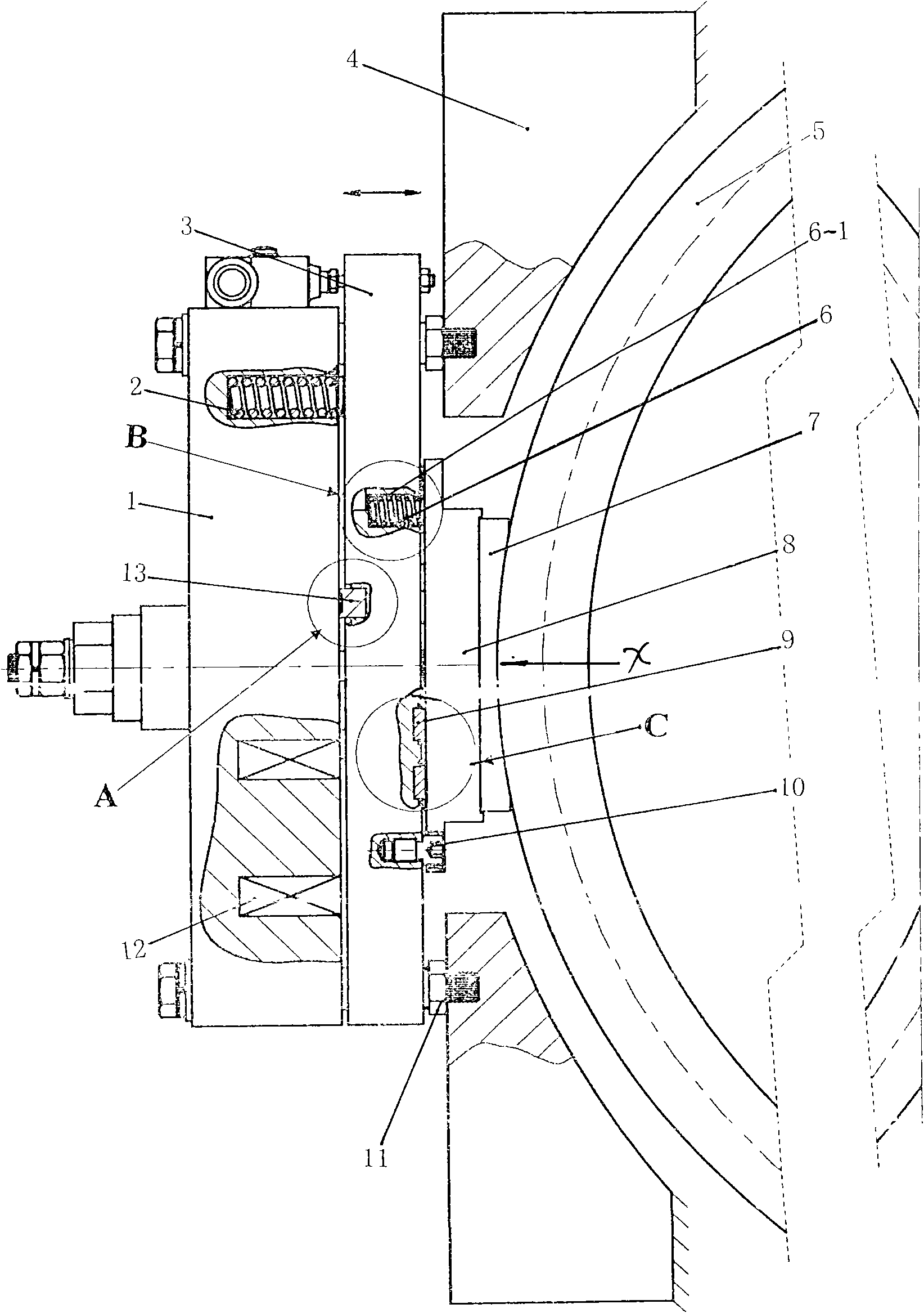
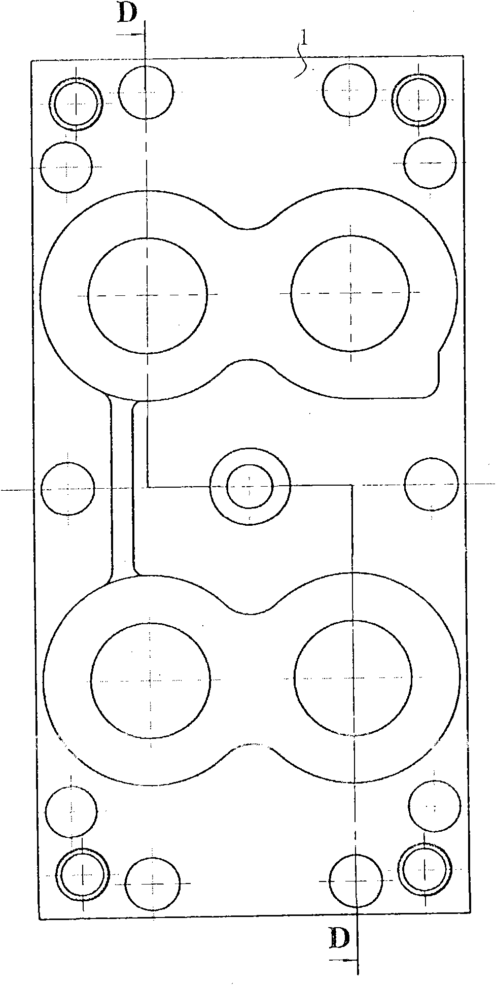
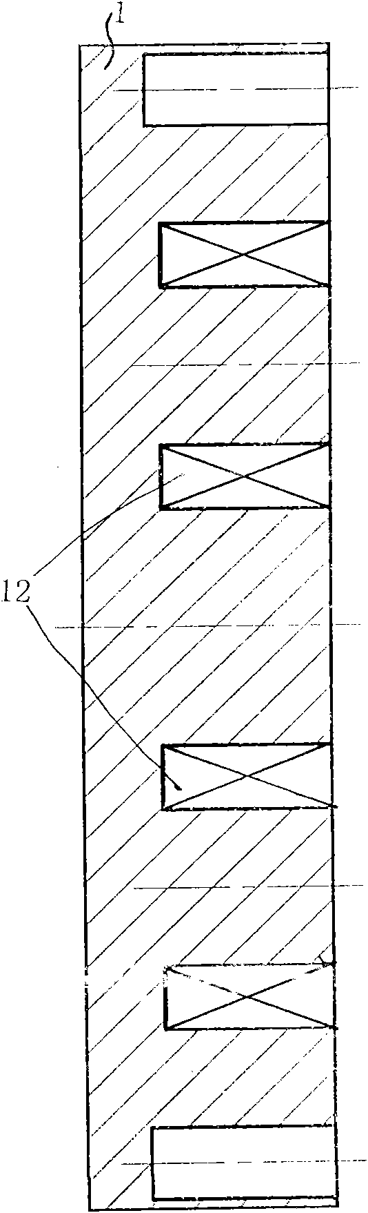
[0038] Figure 1 to Figure 7 Example figures are given. The safety brake of the elevator traction machine in this embodiment includes a grooved disc 1 with a winding coil 12, an armature 3, a compression spring 2 with one end in the spring hole of the grooved disc in contact with one end face of the armature, and a tongue mounted on the other end face of the armature. Plate 8, friction plate 7. Such as figure 2 , image 3 As shown, there are four winding coils on the grooved disk, which are equidistantly distributed on the grooved disk.

[0039] There is an elastic damping pad 13 on the armature relative to the groove plate, and the top of the elastic damping pad stretches out of the armature, and there is a resistance pad 9 on the armature opposite to the tongue plate. The return spring hole 6-1 of the return spring 6 is equipped with the return spring hole 6-1, and the top of the resistance pad extends out of the armature In addition, one end of the return spring is in ...


PUM


Abstract

The invention relates to a safety brake of an elevator tractor, which comprises a tank plate of windings, an armature, a compression spring which is positioned on one end of a spring hole of the tank plate and is in contact with one end surface of the armature, a tongue plate installed on the other end surface of the armature, and a friction piece. The safety brake is characterized in that the number of the windings is 2n; and the windings are symmetrically or uniformly distributed on the tank plate, wherein n is a natural number. The invention has high braking performance, low cost and low noise.

Description

Technical field: [0001] The invention relates to a safety brake for an elevator traction machine, and also relates to various clutch brakes through electromagnetic braking (transmission). Background technique: [0002] Electromagnetic brakes and mechanical brakes, the traditional electromagnetic brake uses a built-in coil winding, which generates (loses) electromagnetic force through the winding (loss) to generate action. In today's fierce market competition, customers' requirements for product cost performance are constantly increasing. While the single coil structure of the traditional electromagnetic brake needs to improve the braking performance, it must increase the volume of the winding coil material and the brake itself, which is accompanied by material costs. rise, power consumption increases and temperature rise increases. Moreover, due to the limitation of the use environment of the traditional electromagnetic brake, when the shape must be square, the winding coil...

Claims


Application Information

Patent Timeline
IPC IPC(8): B66D5/08B66D5/30
Inventor 卢晓蓉焦景凡周小平廖世全黎启华李淑冠肖枭
Owner 成都瑞迪智驱科技股份有限公司
Why Eureka
Try Eureka