Elastic rigid centralizer

A technology of centralizer and centralizing strip, which is applied in the direction of drilling equipment, earthwork drilling, drill pipe, etc., which can solve the problems of limited centering effect of centering, centering of casing string, difficulty in drilling operation or well completion operation, etc., and achieve good centering effect of effect

Inactive Publication Date: 2010-09-08
李越
View PDF0 Cites 10 Cited by
  • Summary
  • Abstract
  • Description
  • Claims
  • Application Information

AI Technical Summary

Problems solved by technology

[0003] There are two types of centralizers commonly used at present. One is elastic centralizers, commonly known as spring centralizers or lantern centralizers, which can better match the size of the wellbore and have strong adaptability, especially when the wellbore is facing special conditions. When the borehole diameter shrinks in a permanent formation or the borehole wall is corroded and collapsed, the borehole diameter expands seriously, the effect of centering or expanding and disturbing the displacement is very obvious, but when the inclination angle is too large, the lateral force increases obviously, especially Especially in highly deviated wells and horizontal wells, the centering effect of simple elastic centralizers is very limited; the other type is rigid support centralizers, which have a relatively definite limit on casing eccentricity , can better overcome the problem of insufficient lateral force of the elastic centralizer, but because the maximum outer diameter of the rigid centralizer is often limited b

Method used


Image

  • Elastic rigid centralizer
  • Elastic rigid centralizer
  • Elastic rigid centralizer

Examples


Embodiment Construction

[0011] The present invention will be described in further detail below in conjunction with the accompanying drawings.

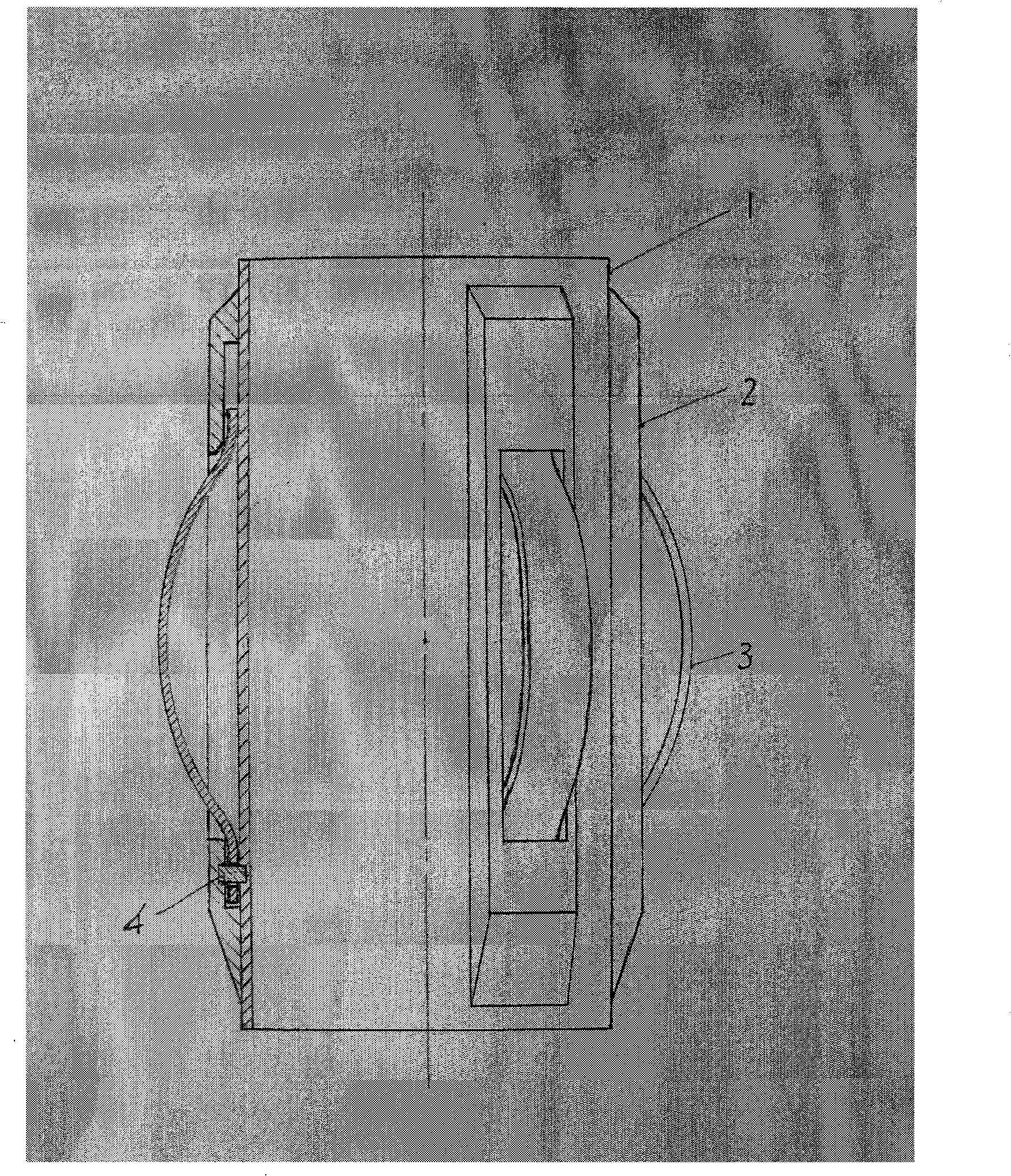
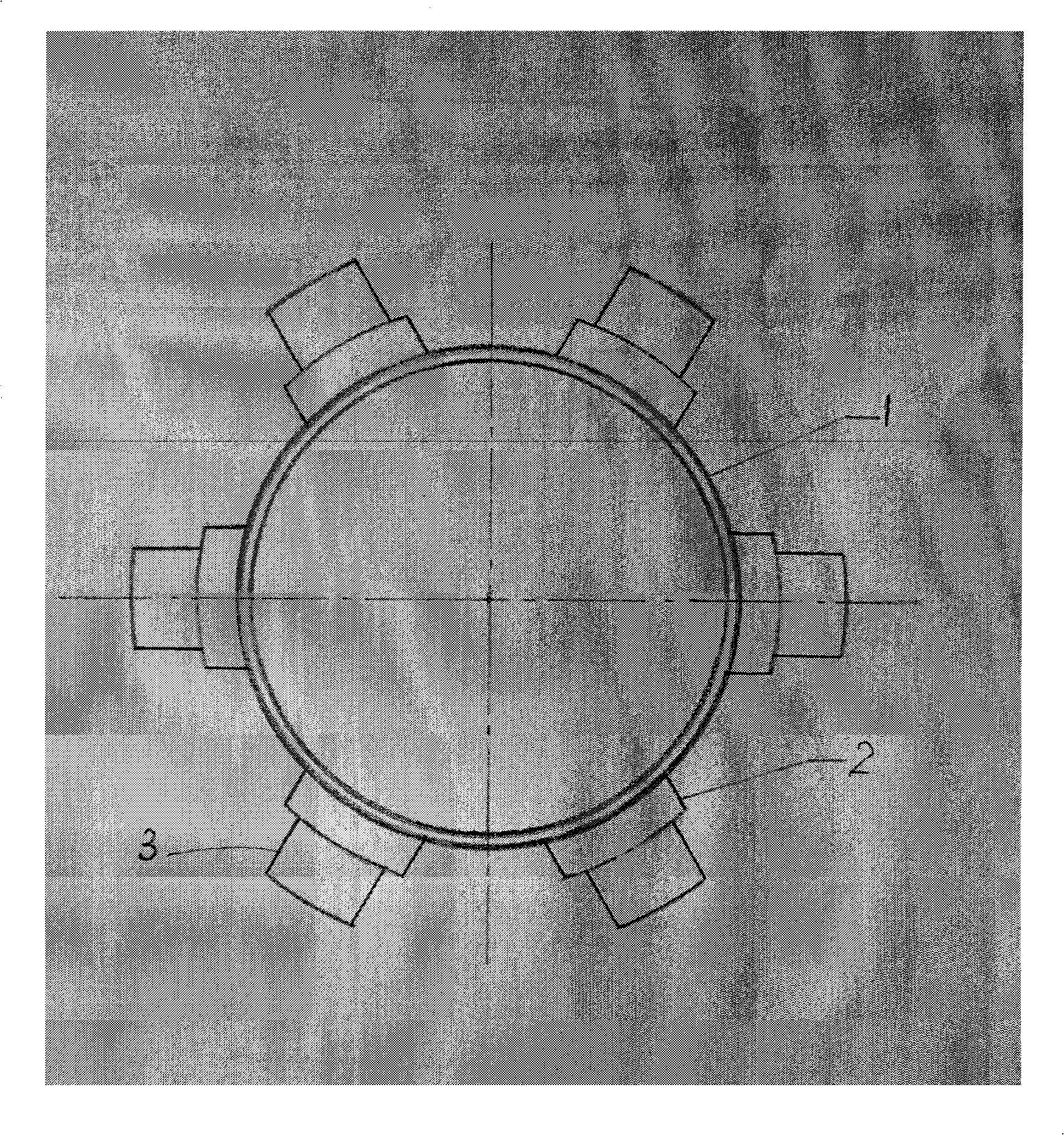
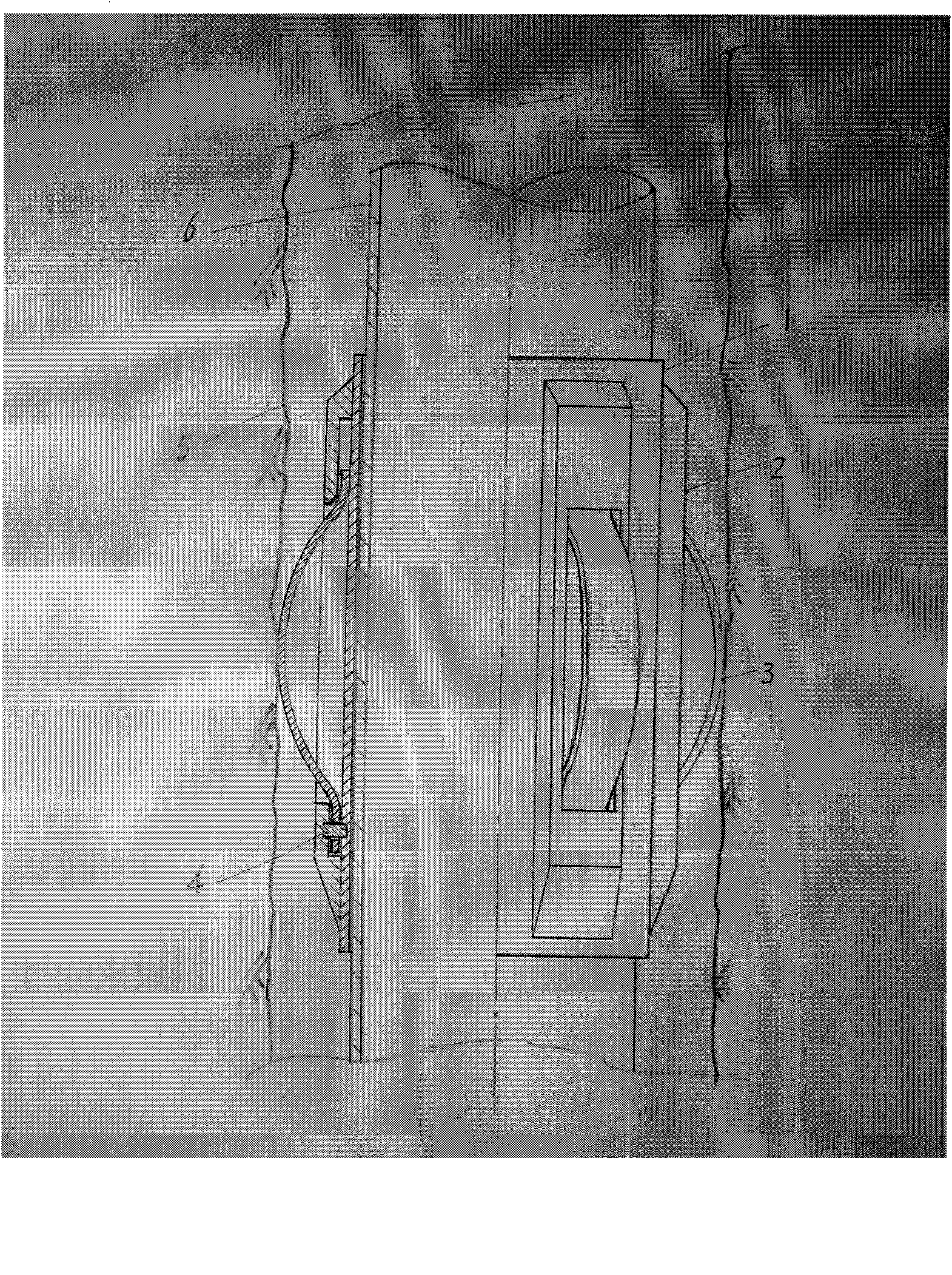
[0012] 1. As attached figure 1 As shown, the present invention mainly consists of a body (1) and several rigid centralizing strips (2) uniformly distributed in the circumferential direction of the body (1). In the groove, one end that enters the well downward is relatively fixed with a lock pin (4), and the other end is a free end that can slide within a limited range in the axial direction in the groove.

[0013] 2. As a further improved embodiment of the invention. Several rigid centralizing strips (2) evenly distributed in the circumferential direction of the body (1) of the present invention are provided with an "inverted T-shaped" chute, and leaf spring centralizing pieces (3) with micro-steps at the end are installed in the groove. It is a free end that can slide within a limited range in the axial direction in the groove.

[0014] 3. As a further im...


PUM


Abstract

The invention relates to an elastic rigid centralizer which mainly comprises a main body (1) , a plurality of rigid centralizing slats (2) and a plurality of plate spring centralizing sheets (3), wherein the rigid centralizing slats (2) and the plate spring centralizing sheets (3) are evenly distributed on the circumference on the main body (1).Each plate spring centralizing sheet (3) is installed in the chute of each rigid centralizing slat (2), thereby forming the novel casing centralizer which has the characteristic of large supporting force of the rigid centralizer and high elasticity of the plate springs. Thus, the invention can restrict the maximum eccentricity and maximally centralize the casing string by using the large centralizing force of the plate springs, thereby ensuring centering. Meanwhile, the integral internal fixation structure prevents the centralizing sheets from shedding, and the peculiar ski function of the cambered plate spring steel sheets can prevent the phenomena of poor casing centering degree and unqualified well cementation caused by decreased centralizer consumption since more casings can result in difficulty in descending the well in the prior well cementation engineering circle. The invention has the advantages of simple structure, reliable performance, high firmness, wear resistance and convenient operation. The invention is suitable for straight wells, and especially suitable for inclined shafts, horizontal wells and slim wells.

Description

(1) Technical field [0001] The invention relates to a centralizer used in well drilling and completion casing cementing engineering construction, in particular to a composite elastic-rigid casing centralizer, which belongs to downhole tools. (2) Background technology [0002] At present, in the cementing process of various drilling projects such as oil, natural gas, salt industry, geothermal and geological mines at home and abroad, it is usually required to keep the casing in the center, so that the cement slurry injected during cementing can improve the displacement efficiency and be the most fully clean and thorough The drilling fluid can be replaced by the ground and evenly distributed in the annular space between the casing string and the well wall to ensure the cementing quality. The commonly used method is to add a centralizer to the casing string. [0003] There are two types of centralizers commonly used at present. One is elastic centralizers, commonly known as spr...

Claims


Application Information

Patent Timeline
IPC IPC(8): E21B17/10
Inventor 李越
Owner 李越
Why Eureka
Try Eureka