Solar heat collector

A technology of solar heat collection and heat collection device, which is applied in the field of solar thermal utilization, can solve the problems of inability to install, cannot be installed horizontally, etc., and achieves the effects of fast hot start, easy split installation, and flexible connection

Inactive Publication Date: 2011-08-10
赵建壮 +1
View PDF0 Cites 0 Cited by
  • Summary
  • Abstract
  • Description
  • Claims
  • Application Information

AI Technical Summary

Problems solved by technology

One is an all-glass vacuum collector, and the other is a heat pipe vacuum tube collector. All glass vacuum collectors are of the water-falling type, which uses the density difference to transfer heat energy to the working fluid. This structure leads to hot water storage. As long as one vacuum tube in the all-glass vacuum tube array is damaged, the entire heat collection device will stop running. In addition, there are solar water heaters that connect and assemble the vacuum tube and the heat storage refrigerator bracket in the market. This structure is used in many Both floors and high-rises cannot be installed, because the existing heat pipe vacuum tubes can only be installed vertically and cannot be installed horizontally (this kind of water heater is realized by using gravity to vaporize the heat pipe, and the liquid flows back down under the action of gravity). It has brought great difficulties to the construction of buildings. The vacuum tube and the heat storage refrigerator bracket are connected and assembled into one solar collector. The thermal effect is good, but it still cannot be installed in cities and towns.

Method used


Image

  • Solar heat collector
  • Solar heat collector
  • Solar heat collector

Examples


Embodiment Construction

[0023] Below with reference to the accompanying drawings, through the description of the embodiments, the specific embodiments of the present invention, such as the shape, structure, mutual position and connection relationship between the various parts, the role and working principle of the various parts, etc., will be further described. Detailed instructions:

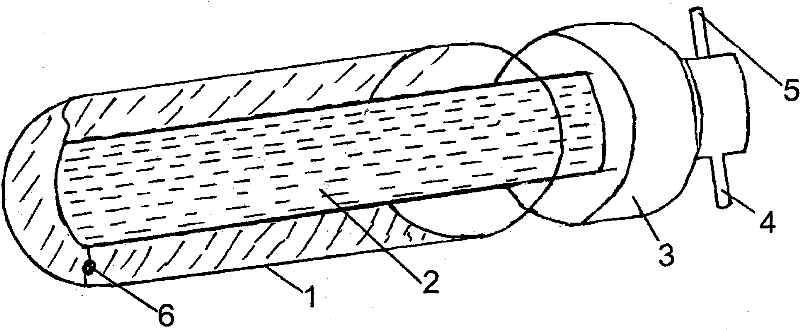
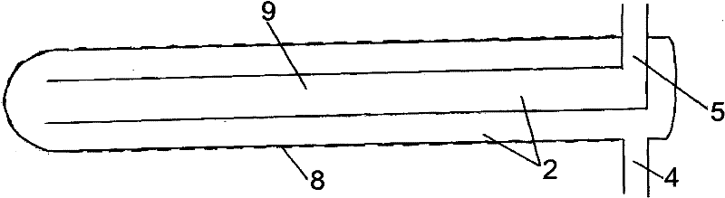
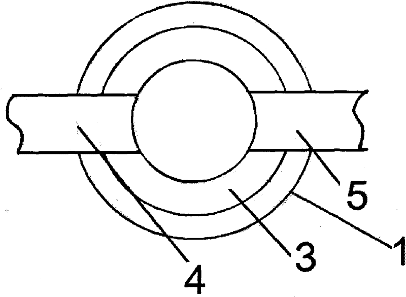
[0024] as attached Figure 1-4 As shown, the present invention is a solar heat collection device, and the solar heat collection device includes a glass tube 1, a metal heat pipe 2, a heat collection device cover 3, and a metal heat pipe end, and the metal heat pipe 2 is arranged as one or more , are all set as a hollow structure, the metal heat pipe 2 is connected to the cover 3 of the heat collecting device, and the metal heat pipe end of the metal heat pipe 2 is set to extend to the other side of the cover 3 of the heat collecting device, and the glass tube 1 is set as a cover The structure that houses the metal hea...


PUM


Abstract

The invention provides a solar heat collector applied in the field of solar heat utilization. The solar heat collector comprises a glass tube (1), one or more metal thermotubes (2), a heat collector cap (3) and metal thermotube ends (4), the metal thermotubes (2) are of hollow structures, and are connected with the heat collector cap (3), the metal thermotube ends (4) of the metal thermotubes (2)are extended to the other side of the heat collector cap (3), and the glass tube (1) covers the metal thermotubes (2), and is of a hollow sealed structure. The technical scheme can be mounted vertically or horizontally, the thermotubes can be conveniently connected in parallel or series, and meanwhile, the heat collector can be more flexibly connected with an exchanger through the thermotubes.

Description

technical field [0001] The present invention relates to the field of solar thermal utilization, and more specifically, the patent of the present invention relates to a solar heat collecting device. Background technique [0002] Existing solar thermal collector mainly has three forms. One is an all-glass vacuum collector, and the other is a heat pipe vacuum tube collector. All glass vacuum collectors are of the water-falling type, which uses the density difference to transfer heat energy to the working fluid. This structure leads to hot water storage. As long as one vacuum tube in the all-glass vacuum tube array is damaged, the entire heat collection device will stop running. In addition, there are solar water heaters that connect and assemble the vacuum tube and the heat storage refrigerator bracket in the market. This structure is used in many Both floors and high-rises cannot be installed, because the existing heat pipe vacuum tubes can only be installed vertically and ca...

Claims


Application Information

Patent Timeline
Patent Type & Authority Patents(China)
IPC IPC(8): F24J2/48F24J2/32F24S10/95
CPCY02E10/44
Inventor 赵建壮
Owner 赵建壮
Why Eureka
Try Eureka