
Whole railway traction locomotive tester

A technology for vehicle testing and railway traction, which can be used in railway vehicle testing and other directions to solve problems such as a large amount of external energy supply.

Active Publication Date: 2010-09-08
HUAZHONG UNIV OF SCI & TECH
View PDF0 Cites 15 Cited by
  • Summary
  • Abstract
  • Description
  • Claims
  • Application Information

AI Technical Summary

Problems solved by technology

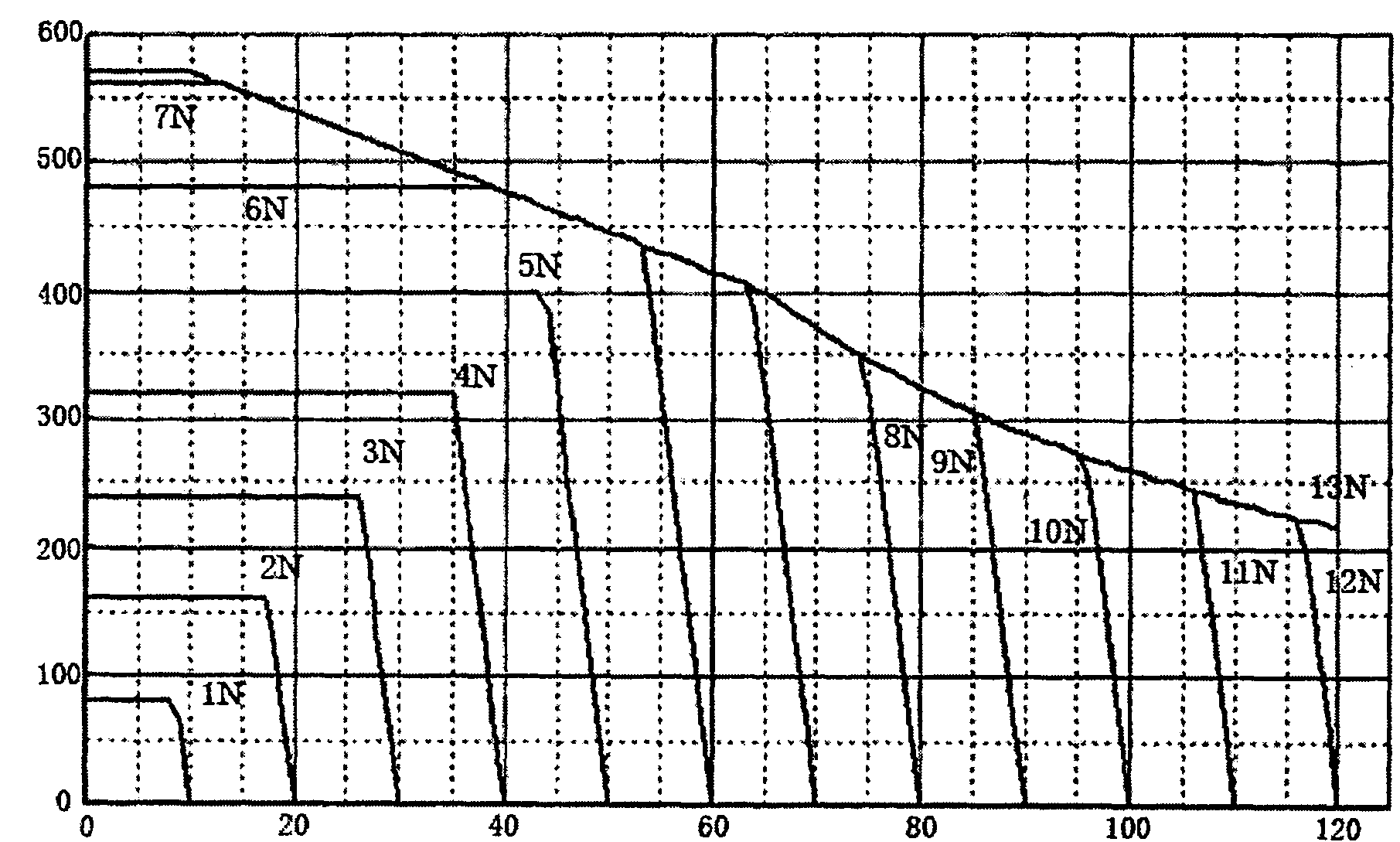
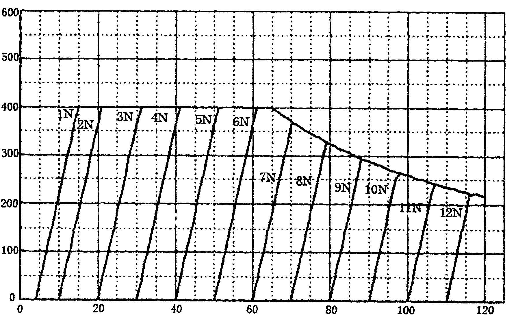
[0005] The invention provides a test device for a railway traction locomotive, which solves the energy consumption problem existing in the existing test device for a complete locomotive, especially the problem that a large amount of external energy supply is required during a locomotive braking test; at the same time, the traction of the locomotive is more realistically simulated / Inertial load characteristics during braking, making the detection results more real and reliable

Method used


Image

  • Whole railway traction locomotive tester
  • Whole railway traction locomotive tester
  • Whole railway traction locomotive tester

Examples


Embodiment Construction

[0041] image 3 Shown is an embodiment of a uniaxial assembly of the present invention. The uniaxial assembly is composed of a track wheel 1 , a universal joint 2 , a synchronous gearbox 3 , a torque sensor 4 , and a flywheel 6 connected in sequence.

[0042] The dimension design of the flywheel 6 connected on the single shaft assembly is carried out below. Assume that the continuous running speed of the locomotive is 65km / h, the maximum speed is 120km / h, the power of the single-axis traction motor is 1600kw, and the mass of the train traction load shared by the single-axis traction motor is 1000T, and the maximum speed of the flywheel corresponding to the maximum speed is 3000 rev / min, then the rotating speed of the continuous speed under the same transmission ratio is about 1600 rev / min. by formula J = 2 · E / N · ω max 2 The calculated flywheel inertia...


PUM


Abstract

The invention relates to a whole railway traction locomotive tester, which belongs to the field of test and control on electric traction locomotive systems. The invention solves the traction and braking problems of the prior whole locomotive tester, and realistically simulates load characteristics in the process of the traction / braking of a locomotive. The tester consists of N sets of single-shaft assemblies, each set of single-shaft assembly comprises railway wheels, universal couplings, synchromesh transmissions, torque sensors and flywheels, wherein N is equal to 4, 6 or 8; and in each set of single-shaft assembly, compensated motors can be connected between the torque sensors and the flywheels. The tester can realistically simulate the load characteristics of a train and carry out a test on traction characteristics, braking characteristics and the like, the flywheels can store electric energy in the process of the traction characteristic test, and can feed the electric energy back to a railway network via a braking mechanism in the braking characteristic test, and thereby energy is efficiently utilized. The characteristics of the train, such as resistance in the process of uphill running, downhill running and stable running, can be simulated by controlling the compensated motors, so that a test result can be more real and reliable.

Description

technical field [0001] The invention belongs to the field of traction motor system test and control, in particular to a traction and braking test device for a railway traction locomotive, which adopts a flywheel as the main equipment. Background technique [0002] In order to ensure the normal and safe operation of railway locomotives, it is necessary to carry out vehicle test tests after the locomotive undergoes major and medium repairs. The existing railway locomotive tests in my country are generally carried out in two ways. [0003] One is to use the motor as the towing load, and change the load of the locomotive by adjusting the output power of the motor to carry out the vehicle test; when the load motor is running as a generator, the locomotive is in the traction state, and the traction power of the locomotive is adjusted by changing the electric power output by the load motor. Measure the traction characteristics at a given torque and speed; when the load motor is run...

Claims


Application Information

Patent Timeline
IPC IPC(8): G01M17/08
Inventor 韦忠朝严志桥黄迪
Owner HUAZHONG UNIV OF SCI & TECH
Learn More