Dual-frequency dual-polarized printing antenna

A printed antenna and dual-polarization technology, which is applied to antenna unit combinations with different polarization directions, antennas, slot antennas, etc., can solve the problems of easy shrinkage, high requirements for manufacturing materials and processes, and single-band antennas. Achieve the effect of facilitating mass production, easy to wear and use, and good functional scalability

Inactive Publication Date: 2010-09-08
SOUTHEAST UNIV
View PDF6 Cites 16 Cited by
  • Summary
  • Abstract
  • Description
  • Claims
  • Application Information

AI Technical Summary

Problems solved by technology

[0002] At present, wearable / worn antennas for human body communication have been reported abroad. There are roughly two types of structures: one is a conductive fabric antenna made in the form of a conventional printed antenna. This type of antenna is easy to bend, shrink, Easy to wrinkle and other problems, the requirements for the production materials and technology are also high; the other is the deformed conventional hard antenna, which makes the antenna conform to the accessories on the clothing, such as buttons, belts, etc., and is made into a part of the clothing. This kind of antenna cannot be integrated planarly and requires machining
On the other hand, the wearable / wearable antennas that have been reported are either used for off-body communication or for body surface communication. This antenna can only work in a single frequency band and single polarization

Method used


Image

  • Dual-frequency dual-polarized printing antenna
  • Dual-frequency dual-polarized printing antenna
  • Dual-frequency dual-polarized printing antenna

Examples


Embodiment Construction

[0015] The preferred embodiments will be described in detail below in conjunction with the drawings, but the scope of protection of the present invention is not limited to the embodiments.

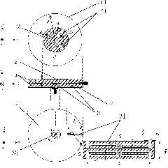
[0016] Embodiment: a dual-frequency dual-polarization printed antenna for human body communication simultaneously working in the 2.40GHz and 5.80GHz frequency bands. Such as figure 1 As shown, the radiating unit 2 and the feeding structure 3 are printed on two layers of polytetrafluoroethylene circular dielectric plates 1 with equal thickness respectively, and the radius of the dielectric plate is R 1 , the thickness is h=1.6mm, the relative permittivity ε r =4.4, the loss tangent value tanσ=0.02; the radiation element 2 is a circular patch; the feeding structure 3 of the antenna adopts two-port feeding, wherein the port 1 is a microstrip line coupling feeding structure 32 along the radial direction, and TM for Exciting Circular Patch 11 Mode, so that it works in the 2.40GHz frequency b...


PUM


Abstract

The invention discloses a dual-frequency dual-polarized printing antenna. The antenna comprises a medium board, a radiation unit, a feed structure and an earthing board, wherein the disc-shaped medium is divided into an upper medium board and a lower medium board; the radiation unit is printed on the upper surface of the upper medium board; the feed structure is printed on the upper surface of the lower medium board; the feed structure is integrated by a disc loaded probe coupled feed structure in the center of the medium board and a microstrip line coupled feed structure along the radius direction; and the earthing board is printed on the lower surface of the lower medium board. The antenna is easy for wearing, can be integrated with other portable equipment, and does not have the problems of buckling, shrinkage, wrinkle and the like.

Description

technical field [0001] The invention relates to a printed antenna, in particular to a wearable antenna for human body communication working in industrial, scientific and medical frequency bands. Background technique [0002] At present, wearable / worn antennas for human body communication have been reported abroad. There are roughly two types of structures: one is a conductive fabric antenna made in the form of a conventional printed antenna. This type of antenna is easy to bend, shrink, Easy to wrinkle and other problems, the requirements for the production materials and technology are also high; the other is the deformed conventional hard antenna, which makes the antenna conform to the accessories on the clothing such as buttons and belts, and is made into a part of the clothing. Such antennas cannot be planarly integrated and require machining. On the other hand, the wearable / wearable antennas that have been reported are either used for off-body communication or body surf...

Claims


Application Information

Patent Timeline
Patent Type & Authority Applications(China)
IPC IPC(8): H01Q1/14H01Q1/38H01Q1/48H01Q13/08H01Q13/10H01Q5/01H01Q21/24H01Q5/10
Inventor 章文勋马达
Owner SOUTHEAST UNIV
Why Eureka
Try Eureka