Gas liquefaction and separation device

A liquid phase separation, gas technology, applied in lighting and heating equipment, liquefaction, separation methods, etc., can solve problems such as pressure loss and low efficiency

Active Publication Date: 2010-09-08
3S GAS TECH LTD
View PDF6 Cites 8 Cited by
  • Summary
  • Abstract
  • Description
  • Claims
  • Application Information

AI Technical Summary

Problems solved by technology

[0007] A disadvantage of this existing device is its relative ine

Method used


Image

  • Gas liquefaction and separation device
  • Gas liquefaction and separation device
  • Gas liquefaction and separation device

Examples


Embodiment 1

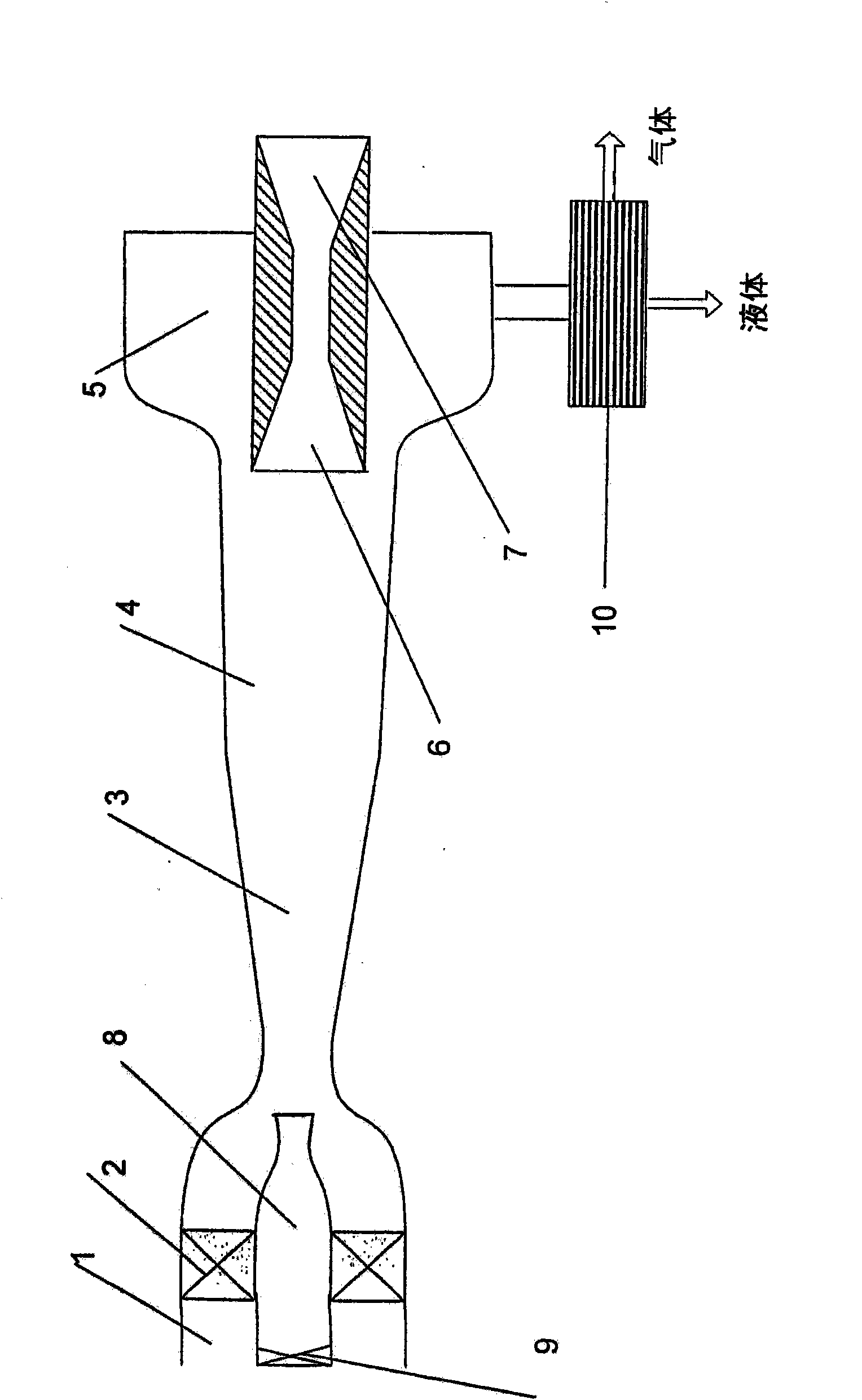
[0052] One embodiment of a gas liquefaction and separation plant, as shown in figure 1 , including the following components coaxially installed in sequence: a premix chamber 1 with a gas flow swirling device 2; an ultrasonic nozzle 3 with a working section 4 attached thereto; a liquid phase separation device 5 attached to the working paragraph. An ultrasonic diffuser 6 and an infrasonic diffuser 7 are arranged downstream of the working section 4 at the outlet of the nozzle 3 . An additional ultrasonic nozzle 8 is placed in the premix chamber 1 of the device, the inlet of which nozzle is provided with means 9 for regulating the gas flow rate in the additional nozzle. The inlet of the additional nozzle is located upstream of the gas flow swirler 2 and the outlet is located in the infrasonic part of the main nozzle. This structural configuration is in principle used for strong initial convolutions. The liquid phase separation device 5 is connected with a gas-liquid separator 1...

Embodiment 2

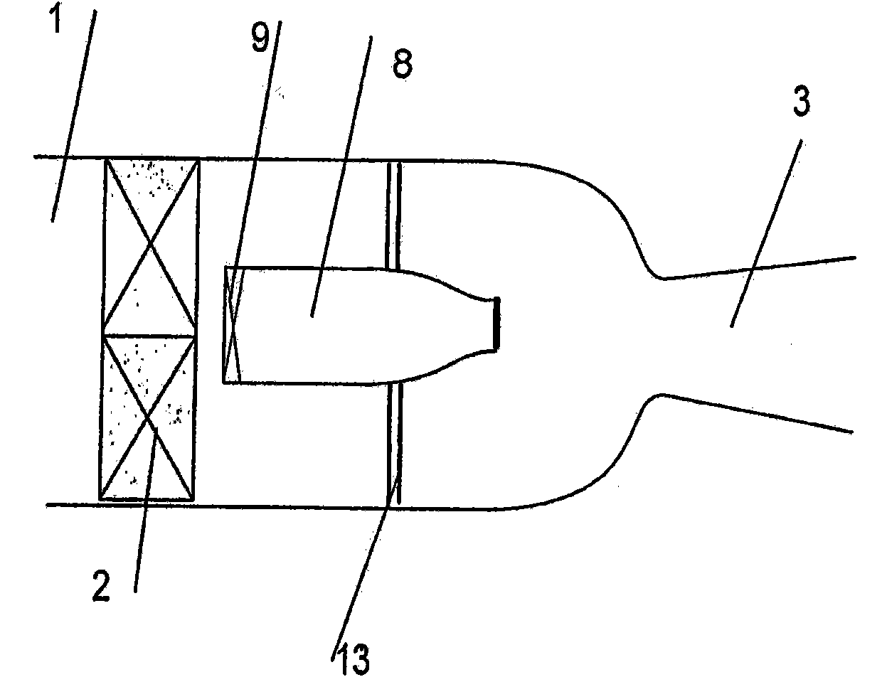
[0066] Another embodiment of the gas liquefaction and separation apparatus, as shown in figure 2 (Only a cross-sectional view of the premix chamber is shown, other elements similar to figure 1 ), including the following components coaxially installed in sequence: a premix chamber 1 with a gas flow swirling device 2; an ultrasonic nozzle 3 with a working section 4 attached thereto; a liquid phase separation device 5 with an attached attached to the working section. An ultrasonic diffuser 6 and an infrasonic diffuser 7 are arranged downstream of the working section 4 at the outlet of the nozzle 3 . An additional ultrasonic nozzle 8 is placed in the premix chamber 1 of the device by means of a rod 13, the inlet of the nozzle being provided with means 9 for regulating the gas flow rate in the additional nozzle. The additional nozzle inlet is located downstream of the gas flow swirler 2 . This structural configuration is in principle used for relatively weak initial maneuvers. ...

Embodiment 3

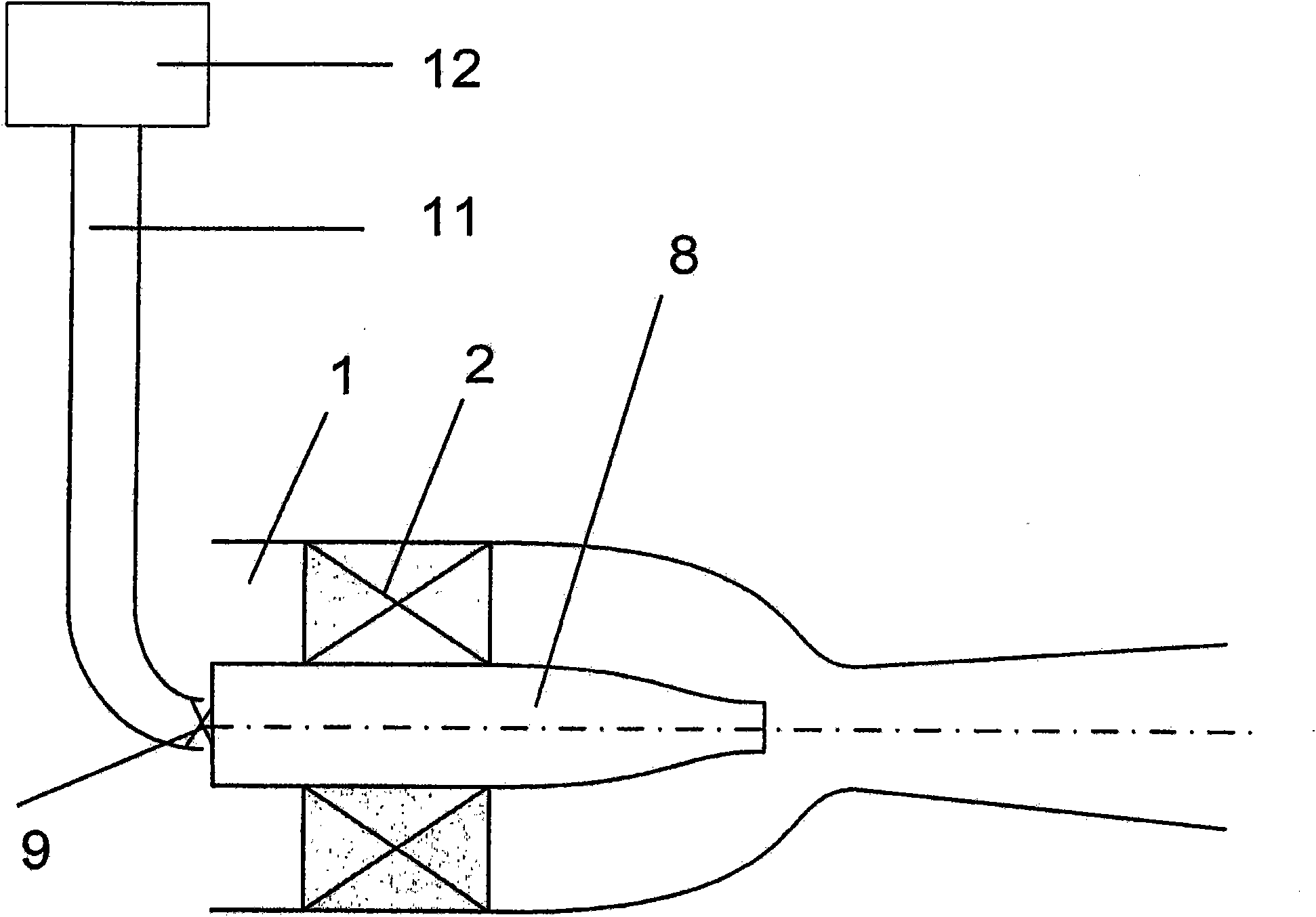
[0074] Yet another embodiment of the gas liquefaction and separation apparatus, as shown in image 3 (Only a cross-sectional view of the premix chamber and external gas source is shown, other components similar to figure 1 ), including the following components coaxially installed in sequence: a premix chamber 1 with a gas flow swirling device 2; an ultrasonic nozzle 3 with a working section 4 attached thereto; a liquid phase separation device 5 with an attached attached to the working section. An ultrasonic diffuser 6 and an infrasonic diffuser 7 are arranged downstream of the working section 4 at the outlet of the nozzle 3 . An additional infrasonic nozzle 8 is placed in the premix chamber 1 of the device, the inlet of which is provided with means 9 for regulating the gas flow rate in the additional nozzle. The additional nozzle inlet is connected via line 11 to an external gas source 12, which may be any known source. For example, it may be an outlet of any appliance for ...


PUM

PropertyMeasurementUnit
Sizeaaaaaaaaaa

Abstract

The invention relates to cryogenic engineering. The inventive device for liquefying and separating gas and for releasing one or more gases from a mixture thereof, comprises, in series axially positioned, a prechamber (1) with gas flow whirling means (2) arranged therein, a subsonic or supersonic nozzle (3) with a working segment (4), which is abutted thereto and to which liquid phase extracting means (5) is connected, and a subsonic diffuser (7) or the combination of a supersonic (6) and the subsonic diffuser (7). The nozzle (3) is designed in such a way that it makes it possible to achieve the ratios, between the inlet and outlet cross-sectional areas and the minimum cross-section thereof, which provides, at the output of the nozzle, a statical pressure and a statical temperature corresponding to the conditions of condensation of gas or target gas mixture components. The length of the working segment (4) is selected according to a condition of forming condensate drops with a size greater than 0.5 mkm and of drifting them, by centrifugal forces, from the axial area of the working segment to the walls of the drop extracting means, and the aperture angle of the working segment (4) is selected such as to maintain the conditions of condensation of the gas or the target components thereof. The device is provided with an additional nozzle (8) arranged in the prechamber. The invention makes it possible to increase the separation efficiency.

Description

technical field [0001] The invention relates to the field of refrigeration engineering and can be used in various industries to generate liquefied gases, and to separate gas mixture components or to separate one or more target components. Background technique [0002] A gas liquefaction plant is known comprising a housing, in the form of horns, with a number of connections arranged in succession in it and provided with a disk with a plurality of nozzles for insulating the expanding gas and reducing its temperature Down to a certain point, a part of the gas becomes liquid at this temperature (see Japanese Patent No. 07071871, classification number F25 J1 / 00, 1995). A disadvantage of this device is its relatively low efficiency. [0003] A device for producing liquefied gas is known comprising an ultrasonic nozzle for cooling the gas by adiabatic expansion of the gas and a liquid phase separation device which is configured such that the nozzle region has a perforated wall def...

Claims


Application Information

Patent Timeline
IPC IPC(8): F25J3/00F25J1/00
CPCB01D53/002B04C3/06B01D53/24B01D5/0048B01D5/0045B01D45/16F25J1/00F25J3/00B01D53/00
Inventor V·I·阿尔费罗夫L·A·巴吉罗夫L·M·德米特里耶夫S·Z·伊迈夫V·I·费金
Owner 3S GAS TECH LTD
Why Eureka
Try Eureka