Control module, control method, brake vacuum servo device and electric automobile

A technology of vacuum boosting and electric vehicles, which is applied in the direction of brake transmission, brakes, brake safety systems, etc. It can solve the problems of vacuum pump loss, brake system safety hazards, and large energy consumption, so as to reduce working time and reduce energy consumption. Consumption, safety-enhancing effects

Inactive Publication Date: 2013-02-06
TIANJIN QINGYUAN ELECTRIC VEHICLE
View PDF0 Cites 0 Cited by
  • Summary
  • Abstract
  • Description
  • Claims
  • Application Information

AI Technical Summary

Problems solved by technology

The vast majority of cars use a vacuum booster braking system. The vacuum source of the vacuum booster device in a traditional internal combustion engine vehicle braking system comes from the intake manifold of the engine. The vacuum power source of the air manifold, the braking force generated by manpower alone cannot meet the needs of vehicle braking, so it is necessary to have an electric vacuum booster to assist manpower in vehicle braking
[0003] At present, many electric vehicles use electric vacuum pumps to evacuate continuously. Although this can achieve brake boosting, it consumes too much energy, increases the noise of the system, and causes premature loss of the vacuum pump.
There are also some systems that use a vacuum pressure switch or a vacuum pressure sensor to control the start or stop of the vacuum pump. Simple control is performed only according to the on-off of the vacuum pressure switch or the output voltage value of the vacuum pressure sensor. There is no diagnostic function, which makes the brake system exist. Security risks

Method used


Image

  • Control module, control method, brake vacuum servo device and electric automobile
  • Control module, control method, brake vacuum servo device and electric automobile
  • Control module, control method, brake vacuum servo device and electric automobile

Examples


Embodiment 1

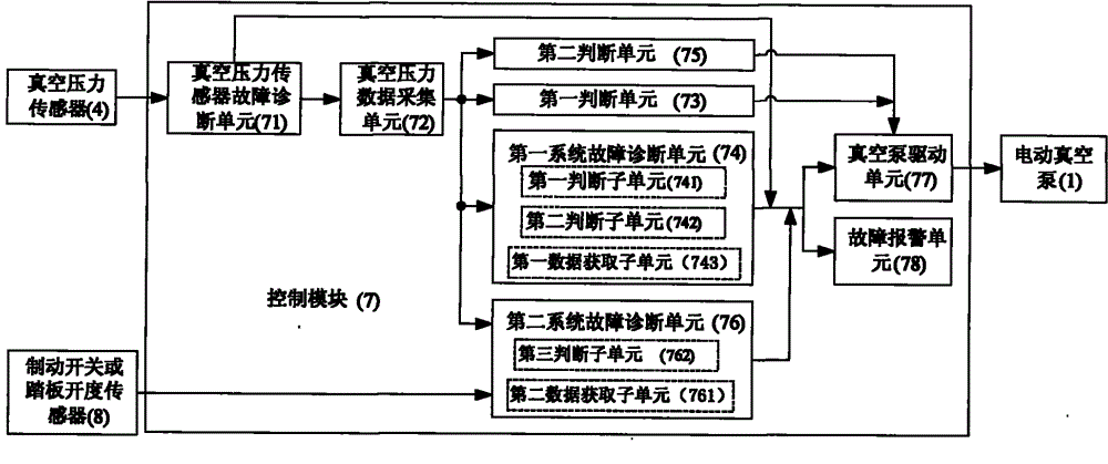
[0022] see Figure 1 ~ Figure 3 , a control module 7 of an electric vehicle brake vacuum booster, the control module 7 includes a vacuum pressure sensor fault diagnosis unit 71 and a vacuum pressure data acquisition unit 72, and the vacuum pressure data acquisition unit 72 is based on the collected vacuum pressure sensor 4 The output voltage value calculates the vacuum pressure value, and the vacuum pressure sensor fault diagnosis unit 71 is used to judge whether the vacuum pressure sensor 4 is faulty, if yes, control the vacuum pump 1 to work and give a fault alarm; if not, the control module 7 also Including a first judging unit 73, the first judging subunit 73 is used to judge whether the vacuum pressure value exceeds the first set value when the vacuum pressure sensor fault diagnosis unit 71 judges that the vacuum pressure sensor 4 is not faulty, and if so , to control the vacuum pump 1 to work, if not, the control module 7 also includes a first system fault diagnosis unit...

Embodiment 2

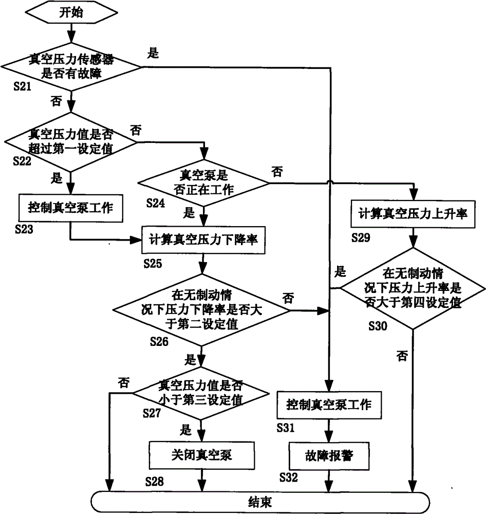
[0038] see Figure 1 ~ Figure 3 , an embodiment of the present invention provides a control method of a brake vacuum booster device for an electric vehicle, the control method comprising the following steps:

[0039] Step S21: Determine whether the vacuum pressure sensor 4 is faulty, if yes, execute step S31 and step S32: control the vacuum pump to work all the time and give a fault alarm; if not, execute step S22;

[0040] Step S22: Determine whether the vacuum pressure value exceeds the first set value, if yes, it indicates that the vacuum degree is insufficient at this time, and execute step S23; if not, execute step S24;

[0041] Step S23: Control the vacuum pump 1 to work;

[0042] Step S24: Determine whether the vacuum pump 1 is working, if yes (when the vacuum pump 1 is working), execute step S25, if not, execute step S29;

[0043] Step S25: Obtain the vacuum pressure drop rate;

[0044] Step S26: In the case of no braking, judge whether the vacuum pressure drop rate...

Embodiment 3

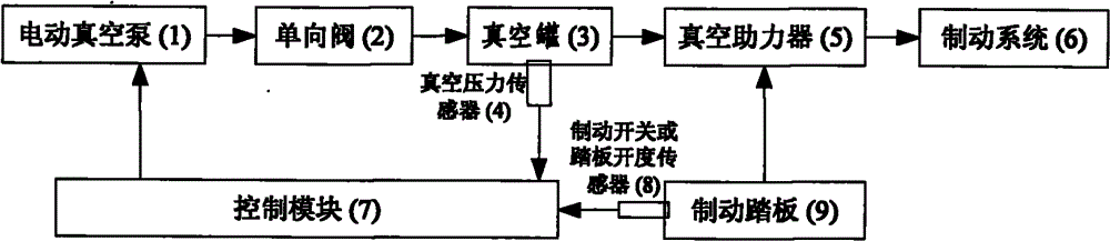
[0056] see Figure 1 ~ Figure 3 , a brake vacuum booster for an electric vehicle, comprising a vacuum booster 5, an electric vacuum pump 1, a vacuum tank 3, a vacuum pressure sensor 4 and a control module 7; the vacuum booster 5 is connected to a brake pedal 9 to provide boost for braking; the vacuum pump 1 communicate with the vacuum servo air chamber of the vacuum booster 5 through the vacuum tank 3, and are used to extract gas from the vacuum servo air chamber; the vacuum pressure sensor 4 is used to measure the air pressure in the vacuum tank 3, and the vacuum pressure sensor 4 and the control module 7 Electrical connection; the structure of the control module 7 is the same as that of Embodiment 1, and its control method is the same as that of Embodiment 2, and will not be repeated here. A brake switch or a pedal opening sensor 8 is provided on the brake pedal 9 for providing braking information to the control module 7 , and the vacuum booster 5 is connected to the brake s...


PUM


Abstract

The invention discloses a control module of a brake vacuum servo device of an electric automobile. The control module comprises a fault diagnosis unit for a vacuum pressure sensor and a vacuum pressure data acquisition unit, wherein the fault diagnosis unit for the vacuum pressure sensor is used for judging whether the vacuum pressure sensor is at fault, and if the vacuum pressure sensor is at fault, a vacuum pump is controlled to work and the fault is alarmed. The invention also discloses a control method of a brake vacuum servo device of an electric automobile. The invention also discloses a brake vacuum servo device of an electric automobile comprising the control module. The invention also discloses an electric automobile comprising the vacuum servo device. In the invention, the fault diagnosis unit is arranged for judging whether the brake vacuum servo device is at fault, and when the brake vacuum servo device is at fault, the control module controls the vacuum pump to work and carries out alarming and prompting, thus the brake vacuum servo device has higher reliability, and the safety of the brake system is improved.

Description

technical field [0001] The invention relates to a control module and a control method, a brake vacuum booster and an electric vehicle including the control module. Background technique [0002] Driven by national policies, financial support and technology, electric vehicles (especially pure electric vehicles) have developed rapidly. The vast majority of cars use a vacuum booster braking system. The vacuum source of the vacuum booster device in a traditional internal combustion engine vehicle braking system comes from the intake manifold of the engine. For the vacuum power source of the air manifold, the braking force generated by manpower alone cannot meet the needs of vehicle braking. Therefore, it is necessary to have an electric vacuum booster to assist manpower in vehicle braking. [0003] At present, many electric vehicles use electric vacuum pumps to evacuate continuously. Although this can achieve brake boosting, it consumes too much energy, increases the noise of th...

Claims


Application Information

Patent Timeline
Patent Type & Authority Patents(China)
IPC IPC(8): B60T8/17B60T13/52B60T17/18
Inventor 赵春明周能辉张广秀李磊
Owner TIANJIN QINGYUAN ELECTRIC VEHICLE
Why Eureka
Try Eureka