Eureka AIR delivers breakthrough ideas for toughest innovation challenges, trusted by R&D personnel around the world.

Hollow roll for roller way

A hollow roller and roller table technology, applied in the direction of rollers, conveyor objects, transportation and packaging, etc., can solve the problems of high labor intensity of operators, large number of welding and repairing rollers, and reducing the yield of steel rails, so as to reduce maintenance time. , Improve the surface quality, reduce the effect of roller consumption

Inactive Publication Date: 2010-09-15
PANGANG GROUP VANADIUM TITANIUM & RESOURCES +1
View PDF6 Cites 4 Cited by
  • Summary
  • Abstract
  • Description
  • Claims
  • Application Information

AI Technical Summary

Problems solved by technology

Optimizing the material of the roller and laser surface treatment are the solutions used in the production of the roller to increase the hardness and wear resistance of the roller surface; while in the process of use, the worn part of the roller surface can only be welded and repaired by manual surfacing welding. It is usually carried out after the wear depth of the worn part reaches a certain level, such as 15-20mm, but the quality of welding repair is not high, and the rolled piece is often scratched
At the same time, the phenomenon of roller wear exists in the entire production line. The number of rollers that need to be repaired by welding is large, the welding time is long, and the labor intensity of the operators is high. It is difficult to complete the maintenance within the maintenance cycle.
As far as the production of steel rails is concerned, the phenomenon of scratching the steel rails by the worn roller table is quite common in the products, and the production standards of the current steel rails are getting higher and higher, whether it is domestic iron standards or foreign EM standards, etc. There are extremely high requirements on quality, which reduces the yield of steel rails
[0004] In addition, since the damaged area of ​​the roller table is very concentrated, it also causes a great waste of resources

Method used


Image

  • Hollow roll for roller way
  • Hollow roll for roller way
  • Hollow roll for roller way

Examples


Embodiment Construction

[0020] The present invention will be further described below in conjunction with the accompanying drawings and embodiments.

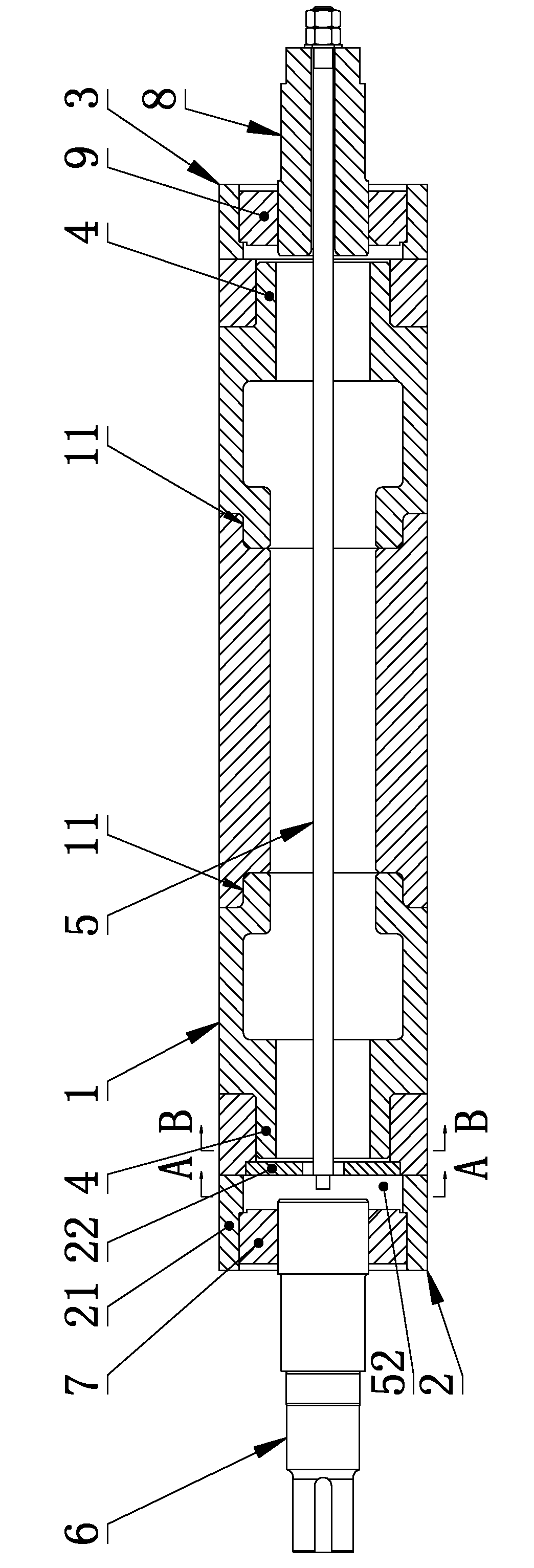
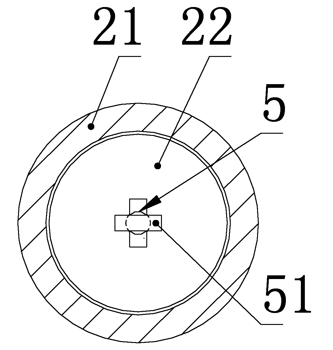
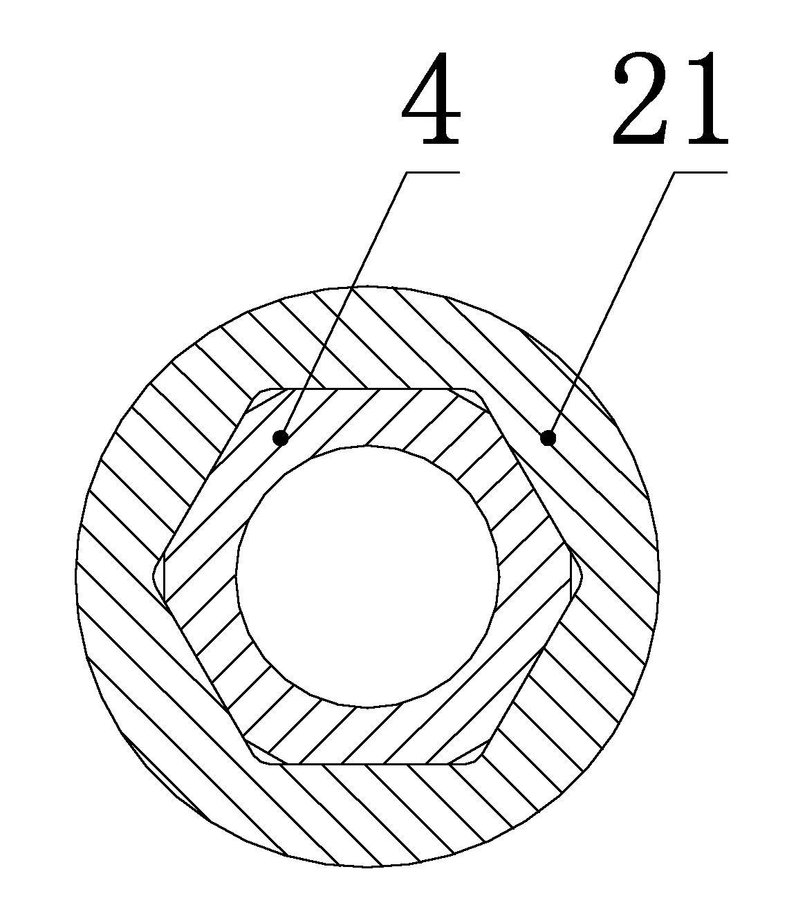
[0021] like figure 1 , figure 2 , image 3 As shown, the hollow roller used for the roller table of the present invention is composed of a roller body 1, a driving side end piece 2, a driven side end piece 3, a driving side shaft head 6, and a driven side shaft head 8. The end piece 2 and the driven-side end piece 3 are respectively positioned at both ends of the roller body 1 through plug-in fit, and the roller body 1, the driving-side end piece 2 and the driven-side end piece 3 are connected as a whole through a detachable fixed connection; The plug fit consists of a mating plug 4 and a socket.

[0022] The wear of the rollers of the roller table is mainly concentrated on the roller body 1, so the transmission side end piece 2, the driven side end piece 3 and the transmission side shaft head 6, the driven side shaft head 8 are still fixed by weldi...


PUM


Abstract

The invention relates to a transportation roller way for sectional material processing, in particular to a hollow roll for a roller way. The hollow roll comprises a roll body (1), a driving side extremity piece (2), a driven side extremity piece (3), a driving side spindle head (6) and a driven side spindle head (8), wherein the driving side extremity piece (2) and the driven side extremity piece (3) are respectively located at two ends of the roll body (1) through grafting type coordination, and the roll body (1), the driving side extremity piece (2) and the driven side extremity piece (3) are detachably and fixedly connected into a whole; the grafting type coordination is formed by a plug (4) and a slot which are coordinated. The invention can realize the rapid maintenance of the roller way, improve the quality of the surface of a rolled piece, reduce the maintenance time, and increase the utilization ratio of a rolling production line and the yield of the sectional material. The replaced roll body is maintained offline and is not influenced by time and fields, which can ensure the quality of the maintained roll body and the surface thereof, thereby the roll consumption is reduced. The invention is suitable for various transportation roller ways.

Description

technical field [0001] The invention relates to a conveying roller table for profile processing, in particular to a hollow roller used for the roller table. Background technique [0002] The transportation roller table is a very critical part in the production of profiles, which plays the role of load bearing and transportation. In production, when the rolled piece passes through the roller table, the surface of the roller table will be worn, and the surface quality of the profile will be greatly affected after the surface of the roller is worn, especially for the transportation of heavy rollers with high quality and high surface accuracy. When high profiles are required. The current roller is usually a hollow roller, which is composed of a roller body, a drive side end piece, a driven side end piece, a drive side shaft head, and a driven side shaft head. The roll body is usually made of seamless steel pipe. Connected as a whole by welding. [0003] At present, there are ...

Claims


Application Information

Patent Timeline
Patent Type & Authority Applications(China)
IPC IPC(8): B65G39/02
Inventor 陶功明刘自彩程铖马胜利吴远洪
Owner PANGANG GROUP VANADIUM TITANIUM & RESOURCES
Why Eureka
Eureka Blog
Learn More