
Method for measuring electric capacity and dielectric loss of capacitance type voltage transformer

A technology of voltage transformer and capacitance, applied in the direction of measuring electricity, measuring devices, measuring electrical variables, etc., can solve the problems of equipment misjudgment, test value fluctuating high and low, power failure loss, etc., to improve sensitivity and effectiveness and confidence, the effect of reducing test error

Active Publication Date: 2010-09-15
广元电业局
View PDF7 Cites 24 Cited by
  • Summary
  • Abstract
  • Description
  • Claims
  • Application Information

AI Technical Summary

Problems solved by technology

Due to the change of equipment status and the influence of factors such as the complex and changeable field test environment, there are many problems in the test. In the field test, the problems in the treatment of the ends of the primary and secondary windings of the medium voltage transformer are particularly prominent, and cannot be analyzed correctly. Handle all kinds of abnormal phenomena, the test value fluctuates
Since CVT is a test product with large capacitance and small dielectric loss, for the film-paper composite insulation structure, the regulations require that its tgδ is not greater than 0.2%. Misjudgment and power failure loss, or the test result of the overall comprehensive dielectric loss is negative, and it is impossible to determine whether the dielectric loss of the capacitor voltage divider is qualified

Method used


Image

  • Method for measuring electric capacity and dielectric loss of capacitance type voltage transformer
  • Method for measuring electric capacity and dielectric loss of capacitance type voltage transformer
  • Method for measuring electric capacity and dielectric loss of capacitance type voltage transformer

Examples


Embodiment Construction

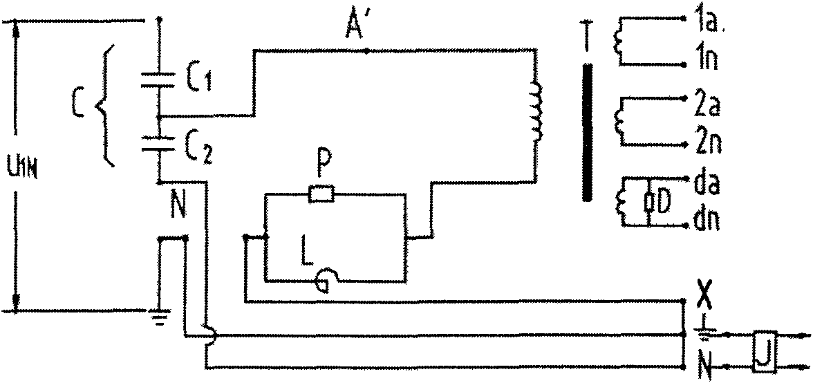
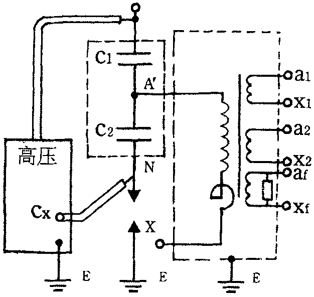
[0021] figure 1 It shows that the CVT uses a capacitor voltage divider to reduce the primary voltage to an intermediate voltage of several thousand to twenty thousand volts, and the intermediate voltage is converted into the required secondary voltage through the medium voltage transformer and realizes the electrical isolation between the primary and secondary circuits. . By adjusting the inductance value of the compensating reactor, the inductive reactance and capacitive reactance of the CVT circuit are 1 / ω(C 1 +C 2 ) are close to equal, thereby greatly reducing the internal impedance of the CVT and improving the load carrying capacity of the CVT. The whole set of CVT is made up of two parts, the capacitive voltage divider and the electromagnetic device. The medium-voltage end and low-voltage end of the capacitor voltage divider are drawn out from the small bushing on the bottom plate of the capacitor at the bottom, and are respectively connected to the high-voltage end of...


PUM


Abstract

The invention relates to a method for measuring the electric capacity and the dielectric loss of a capacitance type voltage transformer, comprising the following steps of: disassembling primary and secondary lead wires of a tested article, and connecting a secondary winding of the tested article to the ground in a short circuit way by a fuse wire; disassembling a lower-voltage terminal X point ofa compensation reactor of the tested article and an end shield to connect to the ground, wherein the end shield and the X point are both suspended in midair; connecting a measuring ground point of a full-automatic digital electrical bridge AI-6000 E to the ground; connecting a high-voltage line and a measuring line to the full-automatic digital electrical bridge AI-6000 E; switching on a main power switch, then switching on an inner high-voltage permitting switch, selecting positive connection wire, inner standard, frequency conversion and testing voltage 10 kV, and finally pressing a starting / pausing key to carry out measurement for more than 1 second; and after the measurement is finished, pressing an up arrow key and a down arrow key to look up data. The invention can effectively reduce measurement errors and is beneficial to objectively and accurately analyzing and evaluating the insulating conditions of equipment.

Description

technical field [0001] The invention relates to a method for measuring capacitance and dielectric loss of a capacitive voltage transformer, in particular to a method for measuring the capacitance and dielectric loss of a capacitive voltage transformer with a single-column structure by using a full-automatic digital electric bridge. Background technique [0002] With the widespread use of capacitor voltage transformers (Capacitor Voltage Transformers, hereinafter referred to as CVT) in power systems, the field test problems are becoming more and more prominent. Most of the current CVTs are single-column structures, and the voltage divider and the electromagnetic unit are stacked as a whole. It is inconvenient to separate the capacitor voltage divider from the electromagnetic unit during the field test. Therefore, the field test is more troublesome and more likely to cause measurement errors. Can't even run a normal test. In the revision instructions of "Preventive Test Regul...

Claims


Application Information

Patent Timeline
IPC IPC(8): G01R27/26G01R31/00
Inventor 罗军川
Owner 广元电业局
Learn More