Industrial frequency resonance transformer

A resonant transformer and transformer technology, applied in the direction of transformers, inductors, electrical components, etc., can solve the problems of high-power variable frequency power supply resonant transformer total cost increase, test frequency deviation from power frequency, test equivalence deterioration, etc., to achieve weight Lightweight, compact and easy to control

Active Publication Date: 2010-09-15
青岛菲特测控节能科技有限公司
View PDF6 Cites 15 Cited by
  • Summary
  • Abstract
  • Description
  • Claims
  • Application Information

AI Technical Summary

Problems solved by technology

[0018] For the resonant transformer with mechanically adjusted air gap, since the electromotive force of the iron core is very large when the reactor is working, especially in the case of large capacity, the resonant transformer with mechanically adjusted inductance has the disadvantages of high noise and unreliable mechanical life.
For the frequency conversion resonant transformer, although the mechanical moving parts are removed, its equivalence will be affected because the frequency of the test power source deviates from the actual operating frequency of the equipment under test, and the cost of the high-power variable frequency power supply will also make the resonant transformer The total cost is greatly increased
[0019] The difficulty in solving the above problems lies in whether the inductance can be continuously and accurately adjusted under static and power frequency conditions.
So far, the improvement of the resonant transformer is mainly on the basis of mechanical tuning, how to reduce noise and improve life through fine machining and better mechanical adjustment mechanism, and frequency conversion tuning is a major improvement measure to achieve static tuning, but its The adverse effect is that the test frequency deviates from the power frequency, which makes the equivalence of the test worse

Method used


Image

  • Industrial frequency resonance transformer
  • Industrial frequency resonance transformer
  • Industrial frequency resonance transformer

Examples


Embodiment 1

[0048] Embodiment 1, in order to realize the mixed AC and DC magnetization of the iron core, the resonant transformer of the present invention includes two identical excitable transformers T1, a rectifier Z connected thereto, an isolation transformer T2 and a controller, and the isolation transformer T2 enables excitation The transformer T1 and the controller realize high-potential isolation, and the controller adjusts the AC excitation impedance of the excitable transformer and the test object through DC bias after detecting the collection current on the primary and secondary sides of the isolation transformer T2 and the output current of the rectifier. The impedance forms a resonance. In this embodiment, current collection is realized through a current transformer CT.

[0049] Figure 4 It is the implementation schematic diagram of a resonant transformer with independent excitation windings. The input and output AC windings of the two transformers T1 are connected in parall...

Embodiment 2

[0050] Embodiment two, Figure 5 It is an implementation scheme of a resonant transformer that superimposes a DC excitation current on an AC winding. This scheme is also composed of an excitable transformer T1, the AC power supply windings are connected in parallel (or in series), and the AC output winding is composed of four coils crossed in series and then connected in parallel (the cross-series and parallel windings can also be set on the power supply side). The AC voltage difference between the two points is zero, and the saturation of the two transformer cores can be controlled by injecting DC excitation current from these two points, so as to achieve the purpose of adjusting the AC excitation current. Figure 5 form of a resonant transformer with Figure 4 The control methods of the resonant transformers in different forms are the same, so I won’t go into details here.

Embodiment 3

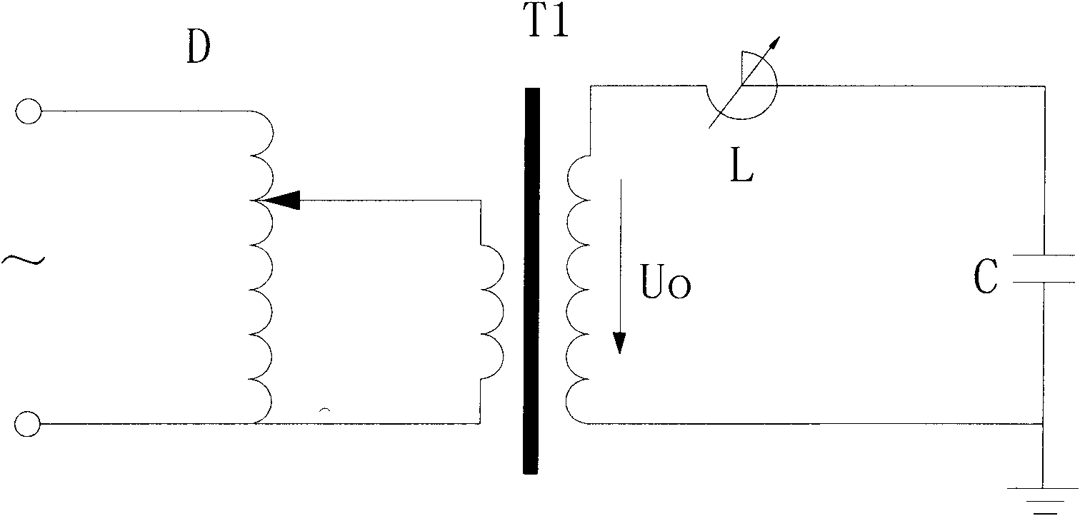
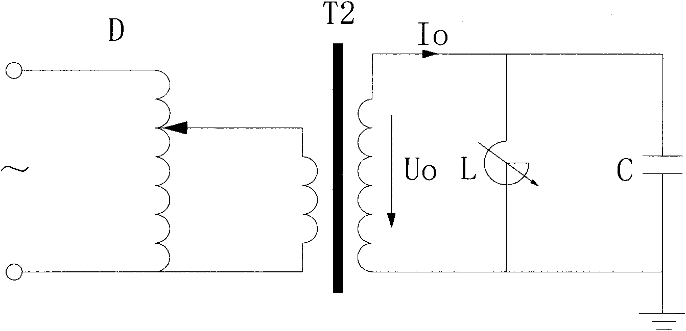
[0051] Embodiment 3, the power frequency resonant transformer of this embodiment, one end is connected to the power supply, and the other end is connected to the tested product, refer to Figure 6 and Figure 7 , which includes a voltage regulator D, an isolation transformer T1, an inductance element L, a rectifier Z, a transformer T2, a controller and a current transformer 1, wherein the primary side and the secondary side of the isolation transformer T1 are respectively connected in series with a current transformer 1, and the regulator The transformer D is connected to the inductance element L through the isolation transformer T1, and the controller adjusts the inductance value of the inductance element L through the transformer T2 and the rectifier Z after detecting the collected current on the primary side and the secondary side of the isolation transformer T1, The inductance element L is connected to the tested product C, and the DC excitation winding and the AC reactanc...


PUM


Abstract

The invention relates to a transformer capable of realizing resonance in industrial frequency under the condition of no mechanical governor mechanism. The technical scheme adopted by the invention is as follows: the transformer comprises an excitation transformer, a rectifier connected with the excitation transformer, an isolation transformer and a controller, wherein the isolation transformer is used to ensure that the excitation transformer and the controller realize high potential isolation; after detecting the collected currents on primary side and secondary side of the isolation transformer and the output current of the rectifier, the controller adjusts the AC excitation impedance of the excitation transformer through DC magnetic bias to form resonance with the impedance of a test. On one side, the industrial frequency resonance transformer can form resonance in industrial frequency, output industrial frequency test voltage, have the same working frequency with the device to be tested and effectively detect the insulation defect of the device to be tested; on the other side, the transformer has the advantages of no moving part, low noise and non-maintaining; and furthermore, the variable-frequency power source with large capacity is not needed, the cost is reduced and the failure rate is low.

Description

technical field [0001] The invention belongs to the field of high-voltage tests, and relates to a power-frequency resonant transformer for power-frequency withstand voltage tests for large-capacitance power equipment. Background technique [0002] When the high-voltage power equipment is in the factory test and the acceptance test after the on-site installation is completed, the power frequency withstand voltage test must be carried out to verify whether the insulation is reliable. Due to the high test voltage, the test current will be very large for power equipment with large ground capacitance, such as power capacitors, cables, SF6 combined electrical appliances, etc., so the test power supply capacity required is also large, which makes it impossible to use ordinary test transformers. Meet the requirements, especially when the test is carried out at the installation site of the equipment, the problem is more prominent. [0003] Since the equipment under test is equivalen...

Claims


Application Information

Patent Timeline
Patent Type & Authority Applications(China)
IPC IPC(8): G01R31/12H01F38/00H01F17/04
Inventor 张宗有李绍全
Owner 青岛菲特测控节能科技有限公司
Why Eureka
Try Eureka