Charging station system of electric automobile and matched charging method thereof

A technology for electric vehicles and charging stations, applied to electric vehicles, battery circuit devices, collectors, etc., can solve the problems of undeveloped layout methods, design specifications and standards, and achieve the effects of providing charging efficiency, novel structure, and low cost

Active Publication Date: 2010-09-15
BEIJING INSTITUTE OF TECHNOLOGYGY
3 Cites 33 Cited by

AI-Extracted Technical Summary

Problems solved by technology

But for such a charging station system, there is no...

Method used

In addition, the charging station system according to the present invention also includes a power supply system, which is used to ensure the electricity demand of auxiliary facilities such as charging station battery charging, battery management and lighting, and to control and process the harmonic pollution of the charging unit , to ensure the stable operation of the charging station.
[0040] As shown in FIG. 1 and FIG. 2, FIG. 1 is a schematic structural diagram of a planar charging station system according to the present invention, and FIG. 2 is a schematic structural diagram of a three-dimensional charging station system according to the present invention. It can be seen from Fig. 1 and Fig. 2 that the electric vehicle charging station system of the present invention takes the workshop for replacing the battery of the electric vehicle and charging the replaced battery as the core, and the internal layout adopts a symmetrical arrangement to make full use of space.
[0052] The charging station system of the present invention can also be a three-dimensional charging station system, and ...

Abstract

The invention provides a charging station system of an electric automobile and a matched charging method thereof. The charging station system comprises an automobile parking region, a battery replacement unit, a battery storage unit, a charging unit, a low-voltage distribution unit and a high-voltage distribution unit, wherein the automobile parking region is used for packing the electric automobile the batteries of which is to be replaced; the battery replacement unit is used for replacing the batteries of the electric automobile through battery replacement equipment; the battery storage unit is used for storing and charging the batteries; the charging unit is used for charging the batteries stored on the battery storage unit; the low-voltage distribution unit is used for supplying power to the charging unit; and the high-voltage distribution unit is used for converting inputted high-voltage power to low-voltage power. The charging station system of the electric automobile in the invention has the characteristics of reasonable layout and novel structure, can realize rapid charging, improve the charging efficiency and simultaneously replace and charge the batteries of multiple electric automobiles, and has the advantages of high economic level and stable running with lower cost.

Application Domain

Technology Topic

Image

  • Charging station system of electric automobile and matched charging method thereof
  • Charging station system of electric automobile and matched charging method thereof
  • Charging station system of electric automobile and matched charging method thereof

Examples

  • Experimental program(1)

Example Embodiment

[0039] In order to enable your examiner to further understand the structure, features and other purposes of the present invention, it is now described in detail in conjunction with the attached preferred embodiments. The illustrated preferred embodiments are only used to illustrate the technical solutions of the present invention, not to limit the present invention. invention.
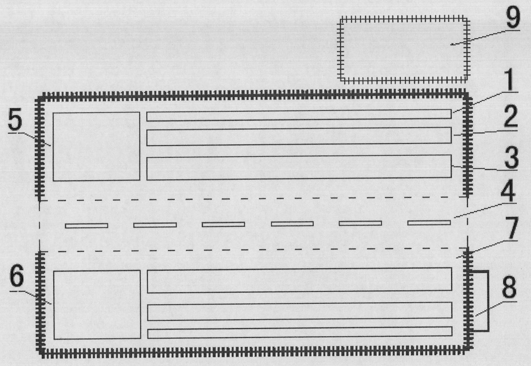
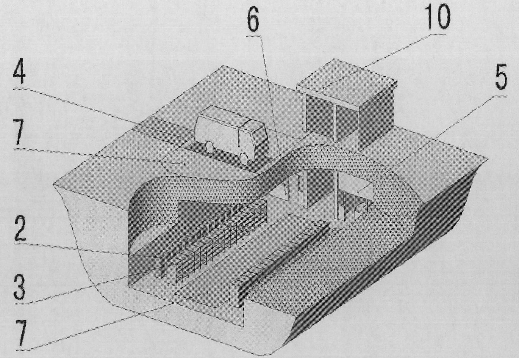
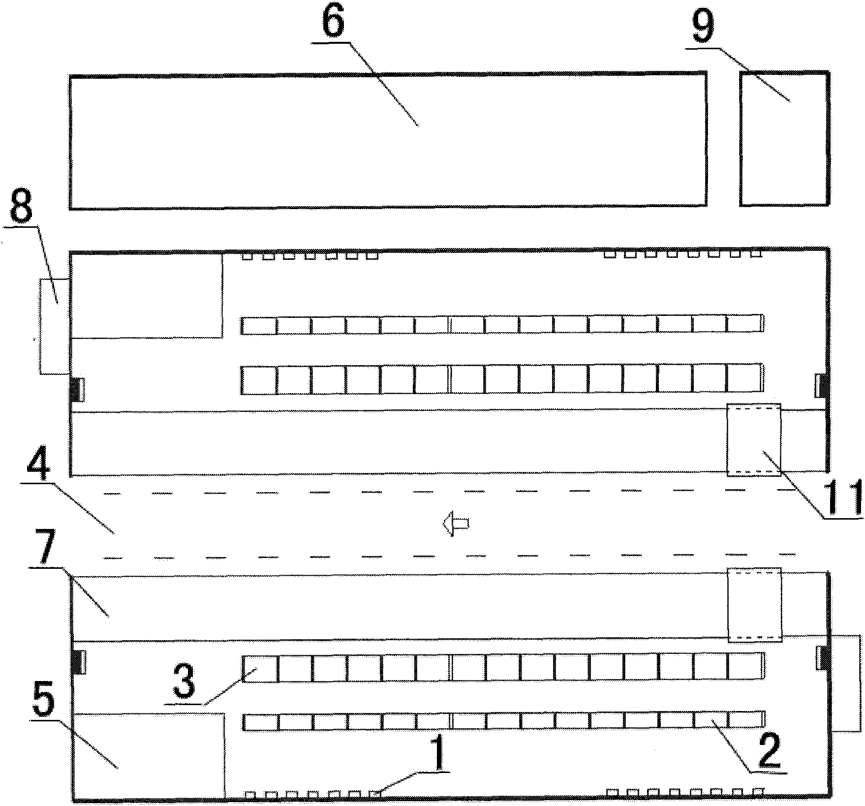
[0040] Such as figure 1 with figure 2 As shown, figure 1 Is a schematic diagram of the structure of the planar charging station system according to the present invention, figure 2 It is a schematic structural diagram of the three-dimensional charging station system according to the present invention. by figure 1 with figure 2 It can be seen that the charging station system of the electric vehicle of the present invention centers on the workshop where the battery of the electric vehicle is replaced and the replaced battery is charged, and the internal layout adopts a symmetrical arrangement to make full use of space.
[0041] When the charging station system of the electric vehicle of the present invention is a flat charging station system, the vehicle parking area 4 is located in the center of the workshop, and the battery replacement unit 7, the battery storage unit 3, the charging unit 2 and the low-voltage power distribution unit are symmetrically arranged on both sides 1, and a high-voltage power distribution unit 9 is provided outside the low-voltage power distribution unit 1 on one side.
[0042] In addition, according to the actual situation of the site, the charging station system may also include a battery maintenance unit 5, a monitoring office unit 6, and a fire fighting facility unit 8. The battery maintenance unit 5, the monitoring office unit 6, and the fire-fighting facility unit 8 are usually distributed in the corner of the workshop or behind the charging unit 2. The voltage, current, SOC and other signals of the battery on the charging unit 2 and the battery storage unit 3 (because the detection of the voltage, current and other signals by the detection device is well known in the art, their detailed description will be omitted here), through the Can bus, etc. The method is transferred to the monitoring platform of the monitoring office unit 6. Fire-fighting facility unit 8 is arranged outside the workshop and adjacent to the workshop, such as a sand pit.
[0043] The functions of each unit will be summarized below.
[0044] The low-voltage power distribution unit 1 and the high-voltage power distribution unit 9 together form a power distribution device, which realizes the conversion of the high-voltage power input from the charging station to the applicable power of the charging device. Among them, the low-voltage power distribution unit 1 is used to provide power to the charging unit 2, and the high-voltage power distribution unit 9 is used to convert the input high-voltage power into low-voltage power.
[0045] Charging unit 2: It is used to charge the battery (for example, by way of trench wiring) to realize the supply of power battery power. It can include charging platform, charging area and charging station monitoring system network interface, etc., because these components are well known in the art Therefore, their detailed description will be omitted here, and they are not shown in the figure.
[0046] Battery storage unit 3: Spare storage space, that is, a place for storing and charging batteries. Generally, a battery storage rack is set for three-dimensional storage of the battery.
[0047] Vehicle parking area 4: Including driving lanes and parking spaces, meeting the parking needs of electric vehicles when replacing batteries and charging, and ensuring continuous and stable operation of replacement. Among them, the charging station has at least two lanes from the entrance to the exit, and the entrance and the exit are set up separately, and they are indicated.
[0048] Battery maintenance unit 5: It is an area used for battery reconfiguration, battery pack balancing, battery pack actual capacity testing, and emergency handling of battery failures.
[0049] Monitoring office unit 6: It is connected to each component unit in a known manner to monitor the operation of the entire charging station system, including power supply system operation monitoring, charging unit operation monitoring, and charging station system safety monitoring.
[0050] Battery replacement unit 7: A functional area that implements the operation of replacing the power battery of the vehicle. Generally, the battery to be replaced from the vehicle is taken out by an equipped automatic mechanical device (such as a robot, etc.) and placed on the battery storage unit 3.
[0051] In addition, the charging station system according to the present invention also includes a power supply system to ensure the power demand of auxiliary facilities such as battery charging, battery management and lighting in the charging station, and to control and deal with harmonic pollution of the charging unit to ensure charging Stable operation of the station.
[0052] The charging station system of the present invention may also be a three-dimensional charging station system, figure 2 It is a schematic structural diagram of the three-dimensional charging station system according to the present invention. by figure 2 It can be seen that the vehicle parking area 4 is set on the ground, the battery storage unit 3, the charging unit 2, the low-voltage power distribution unit 1, and the high-voltage power distribution unit 9 are set under the ground, and the battery replacement unit 7 is set on the ground and under the ground. . Among them, the battery replacement unit 7 arranged on the ground is symmetrically arranged on both sides of the vehicle parking area 4, and the battery replacement unit 7 arranged under the ground is symmetrically provided with a battery storage unit 3, a charging unit 2 and a low voltage distribution unit. Electric unit 1. Since most of the components of the charging station system are located under the ground, space can be used more effectively and land occupation can be reduced. For the three-dimensional charging station system, the elevator equipment 10 can also be arranged at a suitable position.
[0053] The following will combine image 3 The charging station system and the matching charging method for charging electric vehicles using the charging station system according to a specific embodiment of the present invention will be described in detail, wherein: image 3 It is a schematic plan view of an embodiment of a charging station system for an electric vehicle according to the present invention.
[0054] The charging station system according to this embodiment takes a workshop for replacing and charging batteries as the core, and the internal layout adopts a symmetrical structure and a planar layout. The battery on the battery rack is charged through the charging mechanism 2, and the voltage, current, SOC and other signals of the charging mechanism 2 and the battery are transmitted to the monitoring platform of the monitoring office unit 6 through the Can bus, etc., to realize the monitoring of the entire charging process. The monitoring office unit 6 of the charging station system is arranged next to the outside of the workshop. The battery maintenance unit 5 is arranged in two corners at one end of the workshop. The charging station has complete fire-fighting facilities, namely fire-fighting facility unit 8, which includes fire-fighting bunkers. The high-voltage power supply unit 9 is arranged outside the charging workshop.
[0055] The matching charging method for charging an electric vehicle provided by the present invention includes the following: first, the electric vehicle whose battery is to be replaced is parked at a suitable position in the vehicle parking area, and the basic parameters of the charging station system are collected and the design parameters of the charging station system are determined ( For example, the automatic replacement robot 11) performs battery replacement operations for it. Then, the basic parameters and design parameters are transmitted to the system controller terminal, and from the system controller terminal to the low-voltage power distribution unit, charging unit, battery storage unit, vehicle parking area, battery maintenance unit, monitoring office unit, battery replacement The respective controller terminals of the unit, the fire-fighting facility unit and the high-voltage power distribution unit send out information and instructions. Then, according to the information and instructions, the battery replacement equipment waiting for the battery replacement units on both sides will take out the battery to be replaced from the electric vehicle, put it on the battery rack of the battery storage unit, and remove the fully charged battery and install it in On the electric vehicle, the entire replacement operation is completed, and the electric vehicle drives out. Finally, according to the information and instructions, the battery on the battery rack of the battery storage unit is charged and stored by the charging unit.
[0056] The following describes the matching calculation of the number of replacement operators of the charging station system, the number of backup batteries, the number of charging units, service capacity, and power distribution capacity. Using this calculation method can optimize the resource allocation of the charging station system of electric vehicles, improve the economic level of the charging station system, and ensure the stable operation of the charging station system at a lower cost. The calculation method for matching design parameters of charging station system is as follows:
[0057] 1. Basic design parameters:
[0058] Number of replacement operators required per vehicle N g
[0059] Number of vehicles replaced at the same time N t
[0060] Battery charging time T ch
[0061] Operating time for battery replacement per vehicle T ex
[0062] Reserve battery reserve factor C b
[0063] Service time of charging station T qt
[0064] The reserve coefficient C of the front and rear vehicle impact and other links c
[0065] Number of battery changes per day per vehicle N gh
[0066] The number of charging zones required for each battery N d
[0067] Single charging area power P d
[0068] Charging efficiency in charging zone η
[0069] Power factor of charging area
[0070] Coefficient of simultaneous utilization of charging area C t
[0071] 2. Calculation of the main equipment scale, service capacity and power distribution capacity of the charging station system. It mainly includes determining: the number of replacement operators, the number of backup batteries, the number of charging units, the service capacity of the charging station system, and the power distribution capacity. According to the basic parameters that have been determined, the main equipment scale, service capacity and power distribution capacity of the charging station are determined through the following calculation formulas.
[0072] Number of replacement operators N c =N g ×N t
[0073] Number of spare batteries N bat = T ch X N t T ex X C b
[0074] Number of charging zones N cdj =N bat ×N d
[0075] Maximum number of services per day N qs = T qt X N t T ex X 1 C c
[0076] Maximum number of serviceable vehicles N cs = N qs N gh
[0077] The calculation formula for distribution capacity is
[0078] An example of the calculation method for the design parameter matching of the charging station system is given below:
[0079] (1) Battery replacement mode
[0080] The replacement method is an automated robot quick replacement mode. The vehicle to be replaced enters the battery replacement workshop. The robot first removes the battery to be charged from the vehicle, and then removes the fully charged battery from the charging rack and assembles it on the vehicle. The battery-replaced vehicle leaves the battery replacement workshop and enters the starting formation, waiting for the next round of starting. The battery replaced on the charging stand is charged by the charging unit.
[0081] For example, the charging station system according to this embodiment of the present invention adopts a dual-channel solution that simultaneously replaces the batteries of 4 vehicles. The following will take this as an example to illustrate the calculation method of the matching parameters of the charging station system according to the present invention.
[0082] (2) Basic design parameters
[0083]
[0084] Number of items
[0085]
[0086] Replace operator N g 4 people/car
[0087] Number of vehicles replaced at the same time N t 4 vehicles
[0088] Charging time T ch 3 hours
[0089] Replacement time T ex 12 minutes/car
[0090] Reserve battery reserve factor C b 1.2
[0091] Service time T qt 18h
[0092] The reserve coefficient C of the front and rear vehicle influence and other links c 1.2
[0093] Number of battery replacements per car per day N gh 2 times
[0094] The number of charging units required for each battery N d 7 sets
[0095] Single charging unit power P d 9kW
[0096] Charging efficiency of charging unit η 0.9
[0097] Power factor of charging unit 0.85
[0098] Charge unit simultaneous utilization factor C t 0.8
[0099]
[0100] (3) Main equipment scale of charging station
[0101] Number of replacement personnel (person) N c =N g ×N t =4×4=16
[0102] Number of backup batteries (group) N bat = T ch × N t T ex × C b = 3 × 60 × 4 12 × 1.2 = 72
[0103] Number of charging units (unit) N cdj =N bat ×N d =72×7=504
[0104] (4) Charging station service capacity
[0105] Maximum number of services per day (times) N qs = T qt × N t T ex × C c = 18 × 60 × 4 12 × 1 1.2 = 300
[0106] Maximum number of serviceable vehicles (vehicles) N cs = N qs N gh = 300 2 = 150
[0107] (5) Distribution capacity
[0108] The power of the charger in the charging unit is 9kW/unit, and each battery needs to be charged with 7 chargers. According to the experimental data of the charging station, take the charging efficiency of the charging unit η = 0.9, and the power factor Charge unit simultaneous utilization factor C t =0.8, the power distribution capacity is:
[0109]
[0110] (6) Summary of main design parameters
[0111]
[0112] Number of items
[0113]
[0114] Simultaneous replacement capacity (vehicles) 4
[0115] Number of replacement personnel (person) 16
[0116] Number of backup battery packs (groups) 72
[0117] Number of charging units (unit) 504
[0118] The maximum number of battery replacements per day (times) 300
[0119] Maximum number of serviceable vehicles per day (vehicles) 150
[0120] Distribution capacity (kVA) 4744
[0121]
[0122] The charging station system for electric vehicles provided by the present invention has the characteristics of reasonable layout and novel structure, can realize fast charging, provide charging efficiency, and can simultaneously replace batteries and charge multiple electric vehicles, and has a high level of economy. And the advantages of stable operation at lower cost.
[0123] It needs to be stated that the content of the invention and the specific implementations described above are intended to prove the practical application of the technical solutions provided by the invention and should not be construed as limiting the protection scope of the invention. Those skilled in the art can make various modifications, equivalent substitutions, or improvements within the spirit and principle of the present invention. The protection scope of the present invention is subject to the appended claims.

PUM

no PUM

Description & Claims & Application Information

We can also present the details of the Description, Claims and Application information to help users get a comprehensive understanding of the technical details of the patent, such as background art, summary of invention, brief description of drawings, description of embodiments, and other original content. On the other hand, users can also determine the specific scope of protection of the technology through the list of claims; as well as understand the changes in the life cycle of the technology with the presentation of the patent timeline. Login to view more.

Similar technology patents

Electric turntable rail exchanging vehicle

Owner:YANCHENG CITY LONGQIANG MACHINERY MFG

Classification and recommendation of technical efficacy words

  • Reasonable layout
  • Novel structure

Digital controlled temp. regulating automatic water tap

InactiveCN101000111ANovel structureRealize the automation of water temperature adjustmentOperating means/releasing devices for valvesMultiple way valvesAutomatic faucetElectricity
Owner:宁波意耐特阀门有限公司
Why Eureka
Try Eureka