
Phase-shift energy-saving circuit controlled by current

An energy-saving circuit and current control technology, applied in the power supply field, can solve the problems of large waste of resources, high standby power consumption, abnormal operation, etc., and achieve the effect of saving electric energy, facilitating mass production and installation, and simplifying the circuit.

Active Publication Date: 2012-05-23
TEN PAO ELECTRONICS HUIZHOU
View PDF0 Cites 0 Cited by
  • Summary
  • Abstract
  • Description
  • Claims
  • Application Information

AI Technical Summary

Problems solved by technology

[0005] According to the working mode, the power supply can be divided into high-frequency switching power supply and power frequency linear power supply. These two types of power supplies have been developed and produced for many years. It plays an important role in people's life, but these power supplies using traditional technology have relatively high standby power consumption, and the number of such power supplies currently running and in use is hundreds of millions, so a lot of power is wasted in vain. electrical energy
As governments and institutions of various countries have successively promulgated policies and regulations related to energy conservation and emission reduction, power supply manufacturers have designed and produced switching power supply products with a standby power of less than 0.3W or even less than 30mW that can meet the standards, but are generally used to match new For electrical products, these high-energy-consumption power supplies are widely used, and the quantity is huge. If they want to completely replace them in a short period of time, the cost will be quite large, and the waste of resources will be huge, which is very impractical; The noise of the power supply is much larger than that of the linear power supply, which will cause interference to some specific functions and work abnormally

Method used


Image

  • Phase-shift energy-saving circuit controlled by current
  • Phase-shift energy-saving circuit controlled by current
  • Phase-shift energy-saving circuit controlled by current

Examples


Embodiment Construction

[0024] In order to facilitate the understanding of those skilled in the art, the technical solutions of the present invention will be further described in detail below in conjunction with specific embodiments and accompanying drawings.
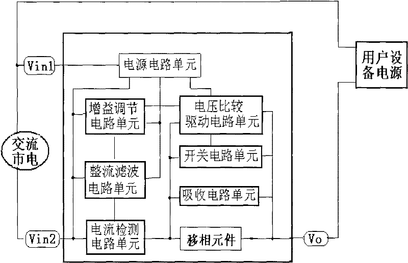
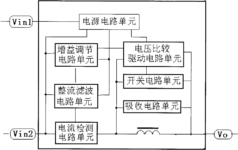
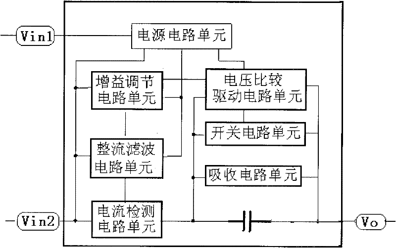
[0025] The design idea of ​​the energy-saving circuit in the present invention is: adopt a phase-shifting element, connect the phase-shifting element in series between the electrical equipment and the AC power supply, and use a switch circuit in parallel with the phase-shifting element, the switch circuit is controlled by Controlled by the current control circuit, the current control circuit controls the on and off of the switch circuit, and then realizes the connection and disconnection of the phase shifting element. The current control circuit includes a current detection circuit unit, a rectification filter circuit unit, a gain adjustment circuit unit, and a voltage comparison drive circuit unit. The output end of the voltage comparison driv...


PUM


Abstract

The invention relates to an energy-saving circuit for reducing the input power consumption of a power supply when the power supply is standby or non-loaded, belonging to the field of power supplies. The energy-saving circuit adopts a phase-shift element; the phase-shift element is connected in series between electric equipment and an AC power supply power supply; a switching circuit is connected in parallel with the phase-shift element and is controlled by a current control circuit; the current control circuit controls the on-off of the switching circuit to realize the switched-on and the switched-off of the phase-shift element; and the current control circuit comprises a current detection circuit unit, a rectifying filter circuit unit, a gain adjustment circuit unit and a voltage comparison drive circuit unit, wherein the output end of the voltage comparison drive circuit unit is connected with the switch circuit unit. The energy-saving circuit as a module can be very conveniently connected between various electric equipment and power supplies to realize the saving of electric energy resources.

Description

technical field [0001] The invention relates to the field of power supplies, in particular to an energy-saving circuit capable of reducing the input power consumption of the power supply when it is in standby or without load. Background technique [0002] Various electronic and electrical products have become an indispensable part of people's life, and a large number of applications of electronic and electrical products have brought huge energy consumption. According to data from the China Energy Administration, in 2009, China's total electricity consumption reached 3,643 billion kwh, a year-on-year increase of 5.96%, and the growth rate was 0.47 percentage points higher than the previous year. Power grid power consumption is increasing significantly, while energy supply is decreasing day by day. In order to deal with this global problem, governments and institutions of various countries, including China, have promulgated policies and regulations related to energy conservati...

Claims


Application Information

Patent Timeline
Patent Type & Authority Patents(China)
IPC IPC(8): H02M7/02H02M1/32
CPCH02J9/005H02M7/05Y02B70/30Y04S20/20
Inventor 洪光岱
Owner TEN PAO ELECTRONICS HUIZHOU
Learn More