
Engine brake detection

A technology of engine braking and engine, applied in the direction of engine control, engine components, combustion engine, etc., which can solve the problems of fuel no longer available, damage to engine cooling, etc.

Inactive Publication Date: 2010-09-15
VOLVO TRUCK CORP
View PDF2 Cites 14 Cited by
  • Summary
  • Abstract
  • Description
  • Claims
  • Application Information

AI Technical Summary

Problems solved by technology

Since the pressure in the exhaust manifold in braking mode is much higher than the pressure in the intake manifold (about 5 bar on the exhaust side and about 1 bar on the intake side), its amount during braking mode depends on the overlapping heat exhaust Gas will flow between the exhaust side and the intake side, which will impair engine cooling during braking mode compared to driving mode, especially since fuel as cooling medium for the nozzles is no longer used during braking mode available

Method used


Image

  • Engine brake detection
  • Engine brake detection
  • Engine brake detection

Examples


Embodiment Construction

[0042] An exhaust pressure regulator for adjusting the exhaust back pressure may be located in the exhaust system after the exhaust manifold but before the tailpipe. The exhaust pressure regulator may be a butterfly regulator, that is, the butterfly regulator is placed in the exhaust system and adjusted by an electric or hydraulic engine so that the opening of the exhaust system can be increased or decreased as required. Opening may be any position between fully open and fully closed, including fully open and fully closed positions. Another restriction within the exhaust system may be the pistons that move in and out of the exhaust system. The open area within the exhaust system is at a maximum when the piston is in its fully external position and may be partially or completely closed when the piston is in its fully internal position. Any position between fully closed and fully open can be selected as desired. Another possible variable restriction means could be a plate inst...


PUM


Abstract

The present invention relates to a method for reducing engine vibrations during engine braking with a malfunctioning engine brake, where said engine brake comprising means for altering a timing of at least one exhaust valve and means for varying an exhaust gas back pressure, comprising the steps of: detecting piston acceleration for each cylinder in the engine during the use of said engine brake,comparing said detected piston acceleration with a predetermined reference value, decreasing exhaust gas back pressure during engine braking if at least one piston is detected with a piston acceleration deviating more than a predefined amount from said predetermined reference value so that said piston acceleration will be falling within said predefined amount from said predetermined reference value.

Description

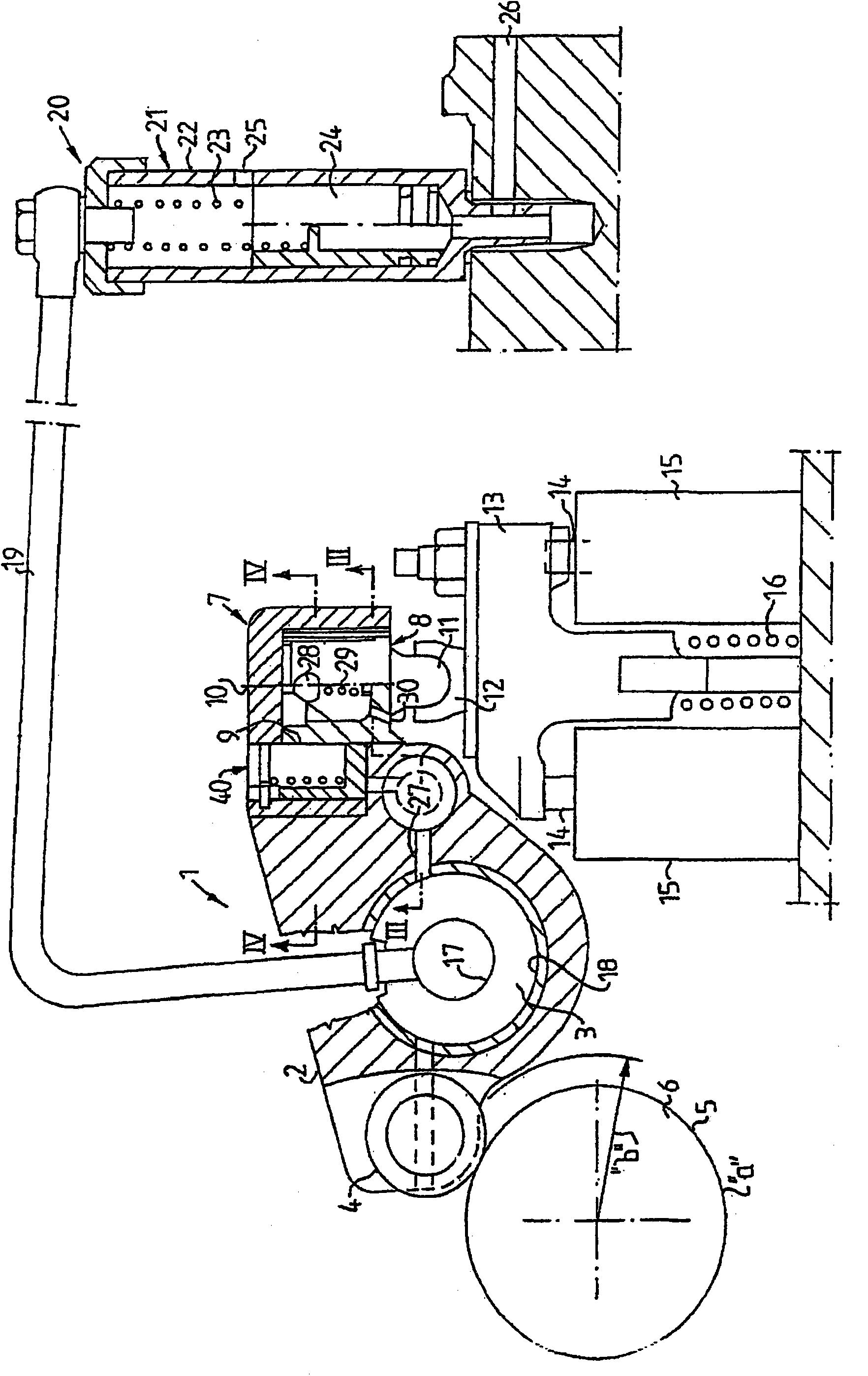
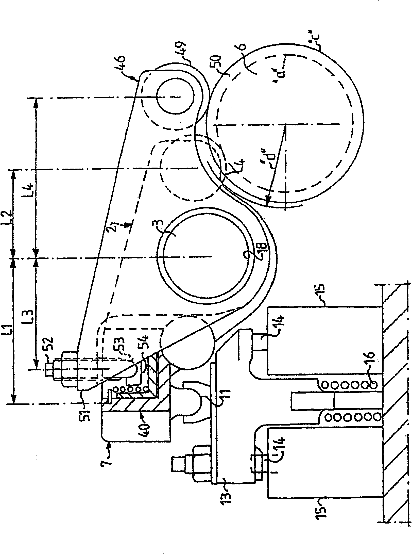
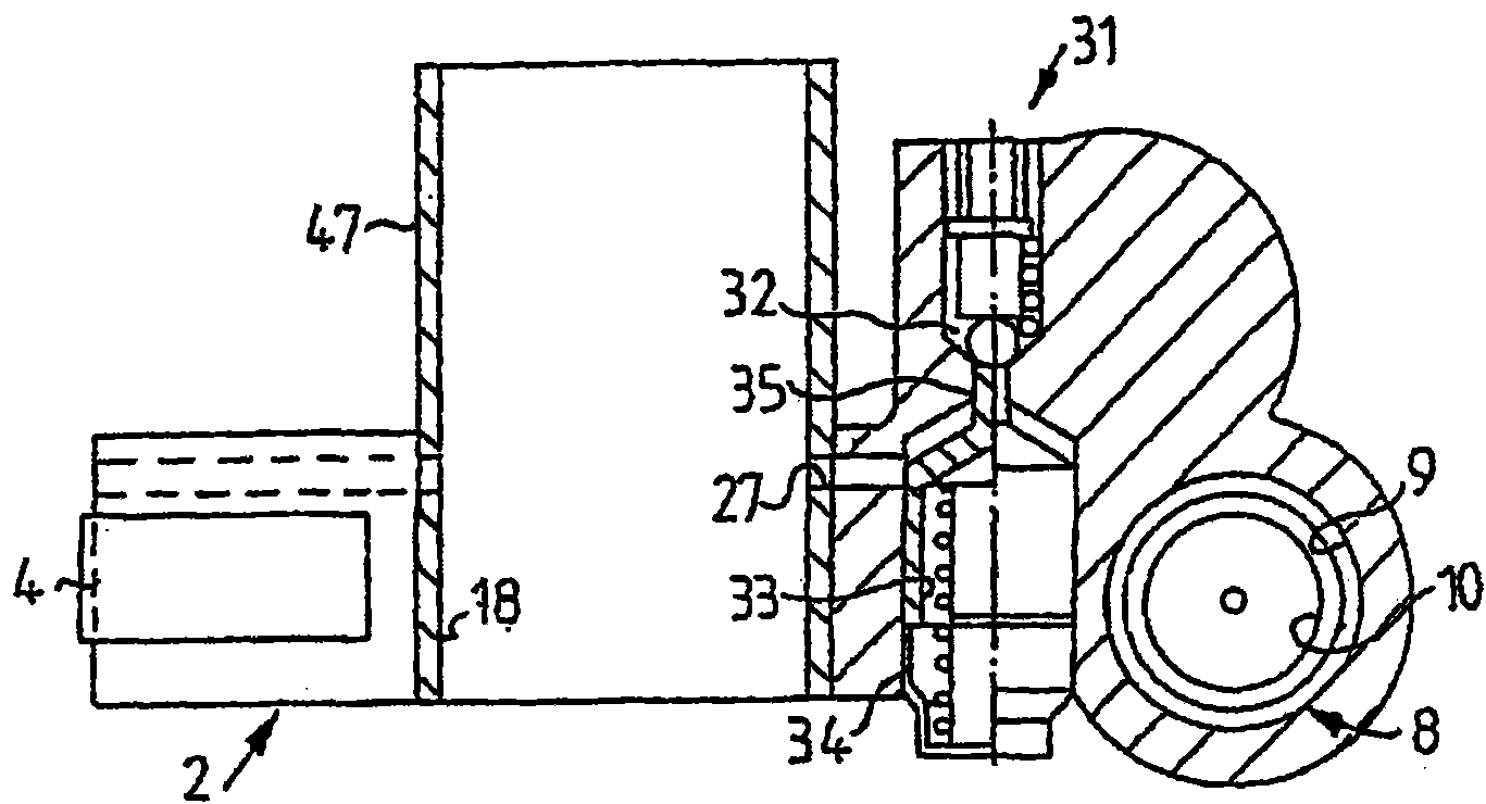
technical field [0001] The invention relates to a method for detecting a faulty engine brake and a method for damping vibrations during engine braking with a faulty engine brake according to the preambles of the independent claims. Background technique [0002] An exhaust valve train in an internal combustion engine comprising: at least one exhaust valve in each cylinder; a rocker arm mounted on a rocker shaft for each cylinder for operating the exhaust valve; with a cam for each rocker arm a camshaft of an element cooperating with a motion transmission mechanism at one end of the rocker arm; a first piston-cylinder arrangement arranged between the opposite end of the rocker arm and the exhaust valve, said first piston-cylinder The device has a first cylinder chamber in said opposite rocker arm end; a hydraulic circuit for supplying and discharging pressurized fluid to and from said cylinder chamber; and a piston disposed in said cylinder chamber, when pressure The piston i...

Claims


Application Information

Patent Timeline
Patent Type & Authority Applications(China)
IPC IPC(8): F02D13/04F01L13/06F02B37/24F02D9/06
CPCF01L2105/00F01L1/181F01L1/08F01L9/026F02D13/04Y02T10/40F01L1/20F01L1/267F01L13/065F02D41/221F01L2820/01F01L9/02F01L2305/00F01L9/16F01L9/10
Inventor 埃里克·奥特约纳什·尼尔森
Owner VOLVO TRUCK CORP
Learn More