Linear motor module for robot splicing

A technology of linear motors and robots, applied in the direction of electromechanical devices, manipulators, electrical components, etc., can solve problems such as insufficient rigidity, limited movement speed and load strength, and cumbersome assembly, so as to improve dynamic response performance, avoid backlash, Responsive and fast effects

Pending Publication Date: 2018-02-23
GSK CNC EQUIP
View PDF6 Cites 10 Cited by
  • Summary
  • Abstract
  • Description
  • Claims
  • Application Information

AI Technical Summary

Problems solved by technology

However, the design and manufacture of linear motors is difficult, and its manufacturing process is complex and difficult to control. Therefore, it is not easy to use linear motors as parts of robots. Therefore, a linear motor that is easy to realize robot splicing is needed. This linear motor While being a part of the robot, it also has the attributes of a module
In addition, existing robots generally adopt transmission structures such as servo motors, reducers, and screw rods. There are many structural transmission parts. This method has disadvantages such as cumbersome assembly, difficult precision assembly, large backlash, inertia, friction, and insufficient rigidity.
And the key components of high-precision reducer and screw are imported; the robot's movement speed is limited by the structure, the movement speed and the load strength are limited, the robot is noisy during operation, and the energy consumption is high. Problems also plague the development of robots.

Method used


Image

  • Linear motor module for robot splicing
  • Linear motor module for robot splicing
  • Linear motor module for robot splicing

Examples


Embodiment

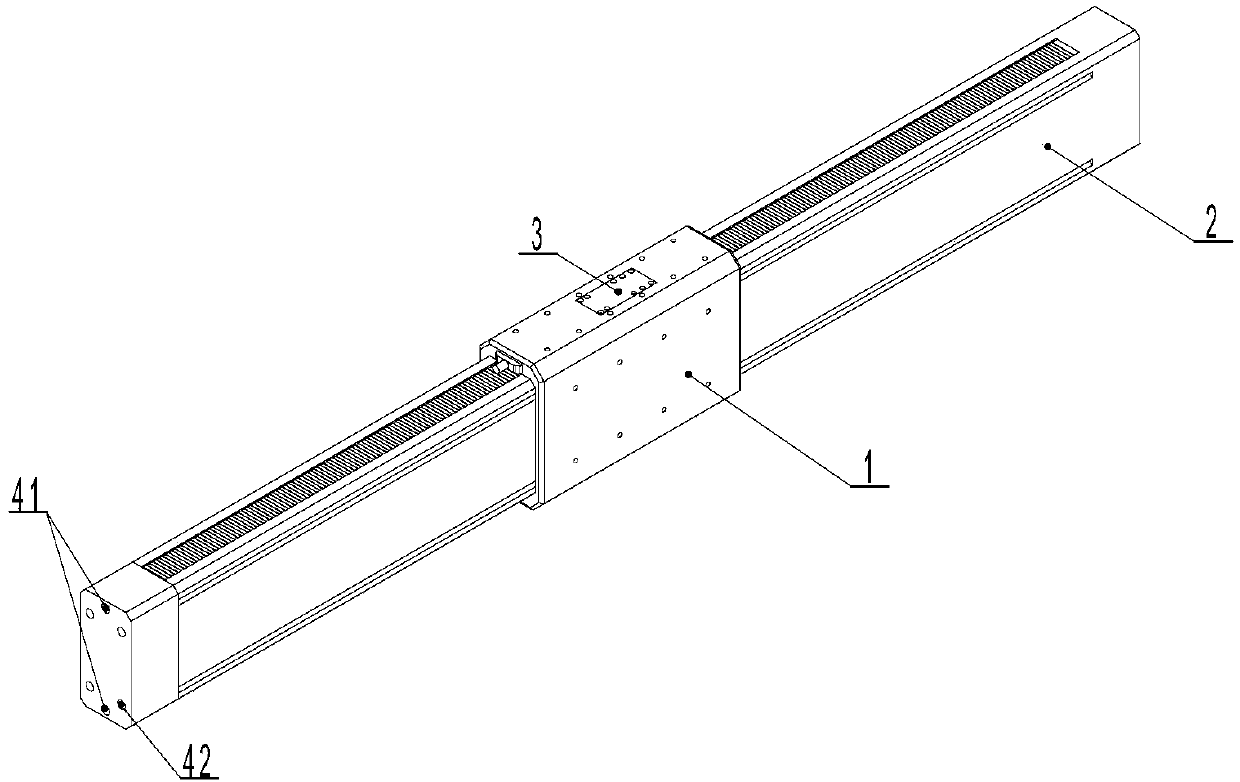
[0032] Such as figure 1 , a linear motor module for robot splicing, including a mover assembly 1, a stator assembly 2, a brake 3 connected to the mover assembly 1, and a controller, the mover assembly 1 is sleeved on the stator assembly 2 On; the moving subassembly 1 and the stator assembly 2 are provided with connecting holes 4;

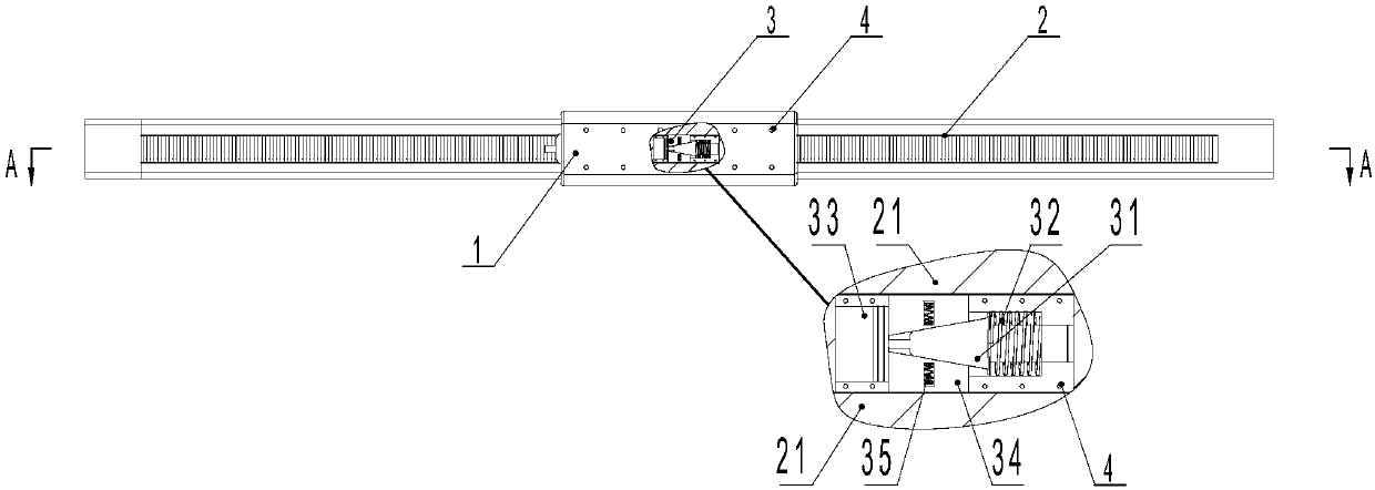
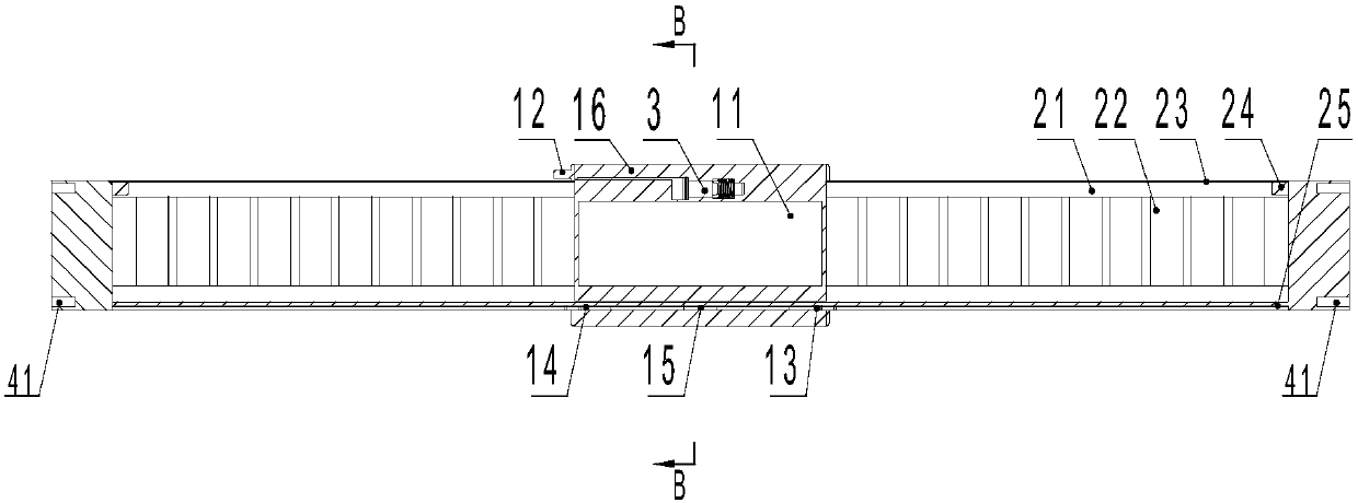
[0033] Such as image 3 , the moving subassembly 1 includes a casing 16, a coil 11, a joint 12, a grating reading head 15, a first limit switch 13 and a second limit switch 14, the casing 16 is sleeved on the stator assembly 2, the The coil 11 is nested in the stator assembly 2, the housing 16 is fixedly connected to the coil 11, the grating reading head 15 is arranged in the middle of the inner wall of the housing 16, the first limit switch 13 and the The second limit switch 14 is respectively arranged at both ends of the housing 16, the connector 12 is fixed on the housing 16, and the connector 12 is electrically connected to the coil 11 or the ...

Embodiment approach

[0058] Several splicing implementation modes of the present invention are as follows:

[0059] Such as Figure 6 , connected into an embodiment of a parallel robot. Fix the stator assembly on the bracket, and attach the arm of the robot to the mover assembly. The figure shows a three-axis parallel robot. In addition to the implementation shown in the figure, it can also be multi-axis parallel, using multiple linear motor modules of the present invention as the drive structure, and each linear motor module is electrically connected to the controller. The motion of each linear motor module is individually controlled by the controller.

[0060] Such as Figure 7 , connected into an embodiment of a Cartesian robot. refer to Figure 7 In the structure shown, the support bar can be a conventional column, or the linear motor module of the present invention can be used as the support bar. Each linear motor module is electrically connected to the controller, and the controller con...


PUM


Abstract

The invention relates to a linear motor module for robot splicing. The linear motor module comprises a rotor assembly, a stator assembly, a brake and a controller, wherein the brake is connected to the rotor assembly, the rotor assembly sleeves the stator assembly, connection holes are formed in both of the rotor assembly and the stator assembly, the rotor assembly comprises a shell, a coil, a connector, a grating reading head, a first limit switch and a second limit switch, the stator assembly comprises a stator body, a permanent magnet and a grating, the brake comprises a wedge-shaped block,a braking spring, a piston, a braking block and an extrusion spring, and the grating reading head, the first limit switch, the second limit switch and the piston all are electrically connected with the controller.

Description

technical field [0001] The invention relates to an automatic control robot, in particular to a robot combination splicing module. Background technique [0002] Existing robots are classified into parallel robots, series robots, and hybrid robots according to the connection mode. Series robots are also called multi-joint robots, which are connected in series through multiple joints and multiple drive shafts; parallel robots can be defined as moving platforms and The fixed platform is connected by at least two independent kinematic chains, the mechanism has two or more degrees of freedom, and is a closed-loop mechanism driven in parallel; the hybrid robot has both serial and parallel modes, and its degree of freedom Many, both series and parallel characteristics. The current robots mostly use rods or plates as the connecting parts of the robot, and use them with drive shafts or drive motors. This combination makes the design and connection of each robot relatively certain, an...

Claims


Application Information

Patent Timeline
Patent Type & Authority Applications(China)
IPC IPC(8): H02K41/02H02K11/22H02K11/20H02K7/102B25J9/00B25J9/08
CPCH02K7/102H02K11/20H02K11/22H02K41/02B25J9/0009B25J9/08
Inventor 钱立江文明
Owner GSK CNC EQUIP
Why Eureka
Try Eureka