Electrostatic-bag composite dust-collector

A technology of electric bag compounding and dust collector, applied in chemical instruments and methods, separation of dispersed particles, filtration of dispersed particles, etc., can solve the problems of not being able to significantly reduce the resistance of filter bags, not being able to improve various defects, and dust being too late to charge, etc. Achieve the effect of reducing equipment maintenance cost, improving cleaning efficiency and prolonging service life

Active Publication Date: 2010-09-22
FUJIAN LONGKING
View PDF0 Cites 12 Cited by
  • Summary
  • Abstract
  • Description
  • Claims
  • Application Information

AI Technical Summary

Problems solved by technology

[0008] However, due to the short residence time of the dust in the electric field area 100, part of the dust has no time to charge; moreover, the distance from the electric field area 100 to the bag field area 200 is longer, and the part of the dust charged in the electric field area 100 is often in a relatively short period of time. During the long distance, it will lose its charge and become a neutral dust again
Therefore, the existing structure cannot significantly reduce the resistance of the filter bag, so that various defects caused by the resistance of the filter bag cannot be improved, and the cost of dust removal is increased.
[0009] In addition, there is a composite dust removal device in the prior art that arranges the electric field channel and the filter bag horizontally, but because the discharge electrode and the filter bag are easy to discharge, it is easy to form an electric spark between the filter bag and the discharge electrode, burning through the filter bag, The quality of dust removal is greatly reduced

Method used


Image

  • Electrostatic-bag composite dust-collector
  • Electrostatic-bag composite dust-collector
  • Electrostatic-bag composite dust-collector

Examples


Embodiment Construction

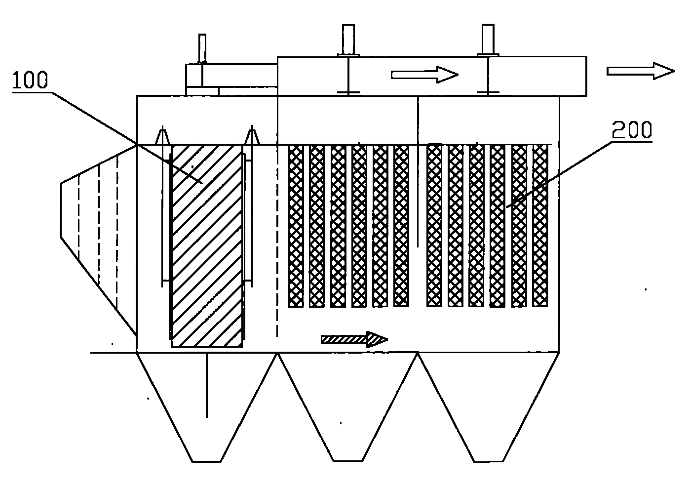
[0034] The core of the present invention is to provide an electric bag composite dust collector, which can not only effectively improve the dust removal efficiency, but also significantly improve the charging rate of the dust before passing through the filter bag, and greatly reduce the time when the dust passes through the filter bag. The resistance, which effectively prolongs the service life of the filter bag and reduces the cost of dust removal.

[0035] In order to enable those skilled in the art to better understand the solution of the present invention, the present invention will be further described in detail below in conjunction with the accompanying drawings and specific embodiments.

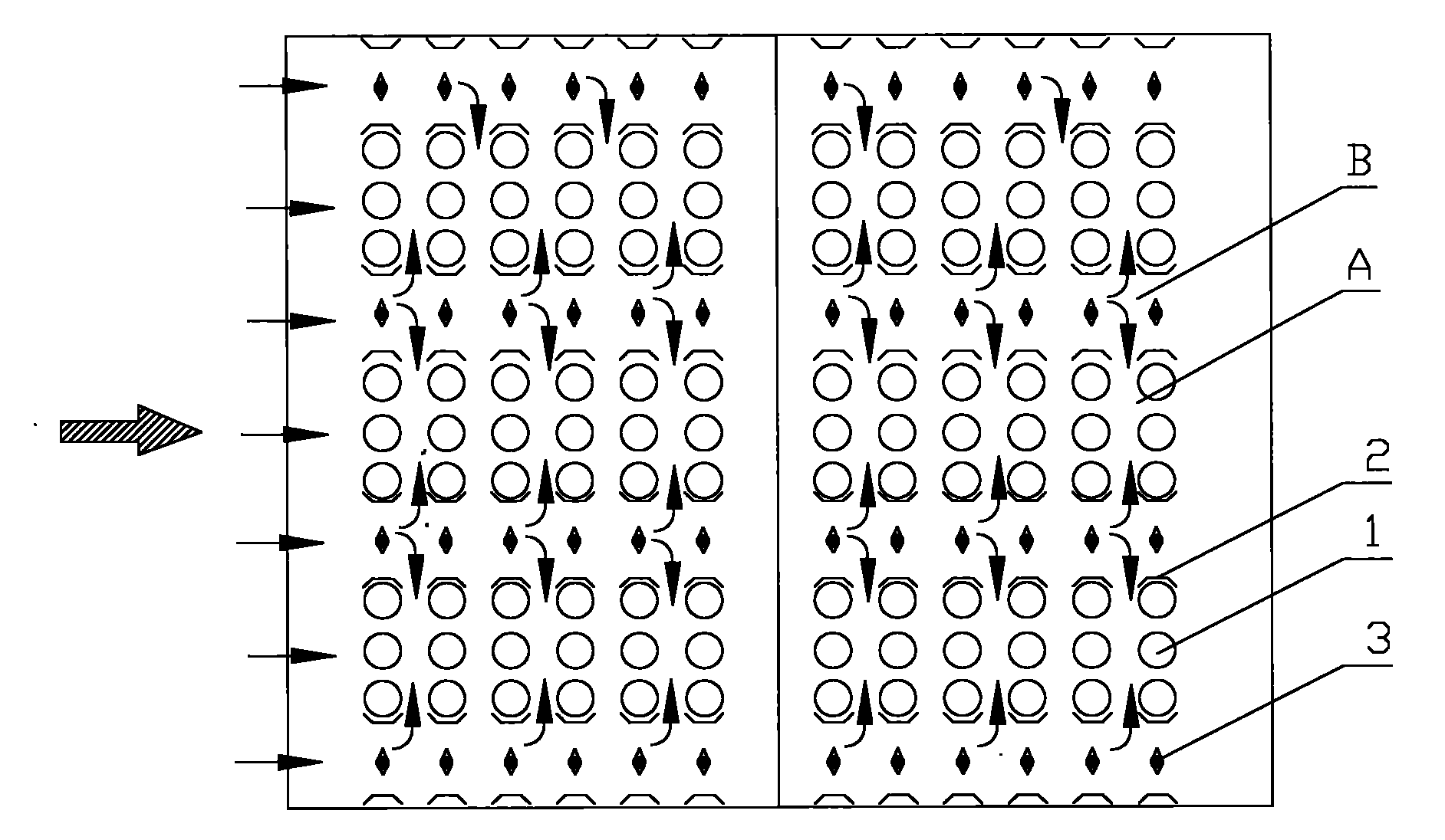
[0036] Please refer to figure 2 , figure 2 It is a top view of a specific embodiment of the electric pocket mixing zone provided by the present invention.

[0037]As shown in the figure, the direction indicated by the arrow in the figure is the flow direction of the flue gas in the...


PUM


Abstract

The invention discloses an electrostatic-bag composite dust-collector comprising an electric-bag mixing area, wherein the electrostatic-bag mixing area consists of a plurality of filtering bag rows and a plurality of electric field channels; each filtering bag row and each electric field channel are generally parallel and are arranged at intervals; each filtering bag row is at least provided with a row of filtering bags (1); each electric field channel is at least provided with two anode plates (2); gaps between adjacent anode plates (2) form an airflow passage; flue gas flowing through the electric field channels enters the filtering bag rows through the airflow passage; one anode plate (2) is arranged on the outer side of each filtering bag (1) adjacent to the electric field channel; and the width of the anode plate (2) is more than or equal to the diameter of the filtering bag (1), so that the filtering bags and discharge electrodes of the electric field channels are separated by the anode plates (2). The electrostatic-bag composite dust-collector not only improves the chargeability of dust and the dust collecting efficiency, but also effectively prevents the filtering bags (1) from being adjacent to the discharge electrodes (3) directly, thereby effectively prolonging the service life of the filtering bags (1) and reducing the cost for dust collection.

Description

technical field [0001] The invention relates to the field of dust collectors, in particular to an electric bag composite dust collector. Background technique [0002] With the continuous improvement of environmental protection requirements, people's requirements for dust removal efficiency are getting higher and higher. At present, the high-efficiency dust collectors (dust removal rate over 99%) widely used in industry include electrostatic precipitators, bag dust collectors, etc. [0003] The electrostatic precipitator works on the principle that the dust is charged in the electric field and deposited on the plate under the action of the electric field force. It only needs 1 to 2 electric fields to collect 70%-80% of the dust. Large-scale power plants are mostly used Electrostatic precipitators. However, the dust removal efficiency of the electrostatic precipitator is greatly affected by the charging performance of the dust. Dust is charged by the thermal motion of elect...

Claims


Application Information

Patent Timeline
Patent Type & Authority Applications(China)
IPC IPC(8): B01D46/02B01D49/00
Inventor 黄炜林宏修海明郑奎照吴江华阙昶兴
Owner FUJIAN LONGKING
Why Eureka
Try Eureka