Automatic tin supplying electric iron

An electric soldering iron and tin supply technology, applied in soldering irons, metal processing equipment, manufacturing tools, etc., can solve the problems of difficult control of solder flow, complicated structure, inconvenient operation, etc., to facilitate mass production, improve production efficiency, and facilitate operation. Effect

Inactive Publication Date: 2010-09-22
张大理
View PDF11 Cites 18 Cited by
  • Summary
  • Abstract
  • Description
  • Claims
  • Application Information

AI Technical Summary

Problems solved by technology

[0003] The invention provides an electric soldering iron with automatic tin supply, which solves the problems of complex structu

Method used


Image

  • Automatic tin supplying electric iron
  • Automatic tin supplying electric iron
  • Automatic tin supplying electric iron

Examples


specific Embodiment approach 1

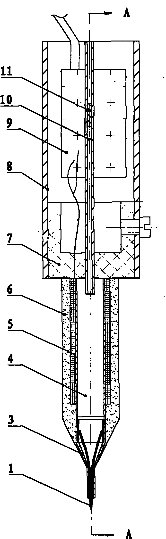
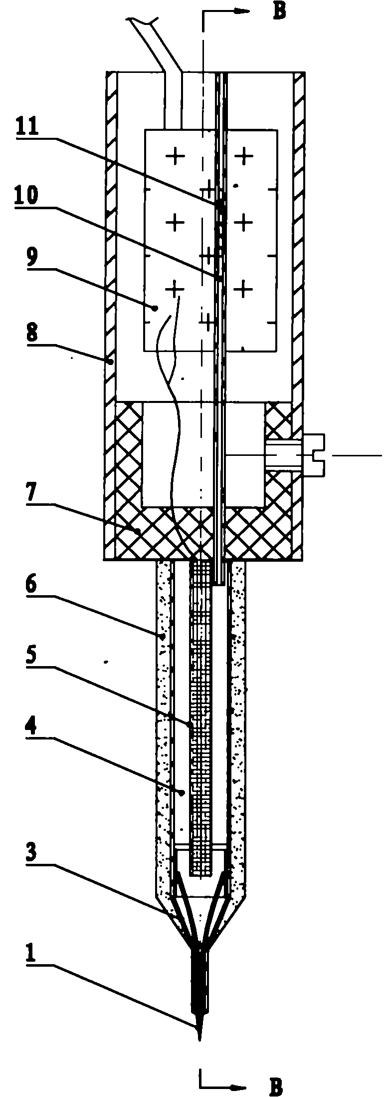
[0018] Embodiment 1: The automatic tin-supply electric soldering iron described in this embodiment includes a wire feeding device, a heating device, a handle 8 and a soldering iron tip, and also includes a tin melting cavity 4, which is located between the handle 8 and the soldering iron tip , the heating device is located inside or outside the tin melting chamber 4, the heating device is used to heat the tin melting chamber 4, and then melts the solder in the cavity; the wire feeding device is used to send the solder wire into the tin melting chamber 4 , the outlet of the melting tin cavity 4 communicates with the inlet of the soldering iron tip; the molten solder enters through the inlet of the soldering iron tip and flows out from the outlet.

[0019] When the automatic tin-supply electric soldering iron described in this embodiment is actually produced, a heat insulating device 7 should be fixed between the handle 8 and the tin melting chamber 4, so as to prevent the heat g...

specific Embodiment approach 2

[0020] Embodiment 2: The difference between this embodiment and the automatic tin-supply electric soldering iron described in Embodiment 1 is that the wire feeding device is located in the handle 8 .

specific Embodiment approach 3

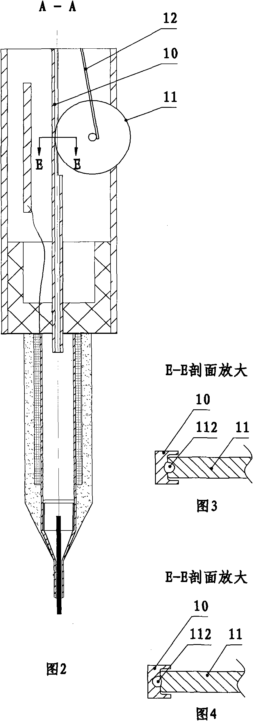
[0021] Specific embodiment three: the difference between this embodiment and the automatic tin-supply electric soldering iron described in specific embodiment two is that the wire feeding device is composed of a wire feeding wheel 11, an elastic device and a wire feeding guide rail, and the axle of the wire feeding wheel 11 It is fixedly connected with one end of the elastic device, and the elastic device presses the edge of the wire feed wheel 11 on the wire feed guide rail, and there is a wire feed channel between the wire feed wheel 11 and the wire feed guide rail, and the wire feed channel can be connected with Solder wire interference fit, part of the edge of the wire feed roller 11 is exposed outside the handle 8, one end of the wire feed guide is located at the edge of the handle, the hard guide is connected to the outside, and the other end of the wire feed guide is located in the melting chamber 4 entrances.

[0022] see figure 2 , is a specific embodiment of the wi...


PUM


Abstract

The invention provides an automatic tin supplying electric iron and relates to the electric iron. The electric iron solves the problems of complicate structure, difficult control of soldering tin flow and inconvenient operation in the conventional automatic tin supplying electric iron. The automatic tin supplying electric iron comprises a heating device, a handle, a solder tip, a tin melting cavity and a wire feeding device. The tin melting cavity is positioned between the handle and the solder tip; the heating device is positioned inside or outside the tin melting cavity; the heating device is used for heating the tin melting cavity so as to melt soldering tin in the cavity; the wire feeding device is used for feeding soldering tin wires into the tin melting cavity; the outlet of the tin melting cavity is communicated with the inlet of the solder tip; and the solder tip can consist of a tin storing cavity and a tin discharging pipe, and can also consist of the tin storing cavity and a brush. The electric iron also comprises an elastic compression device. The automatic tin supplying electric iron has an external heating structure or an internal heating structure. The electric iron has the advantages of simple structure, low cost, convenient mass production and easy popularization.

Description

technical field [0001] The invention relates to an electric soldering iron. Background technique [0002] When the existing electric soldering iron is soldering components, the solder and the electric soldering iron are separated. During operation, one needs to hold the electric soldering iron and the other hand holds the solder. During the soldering process, both hands need to cooperate closely to complete the soldering work. This way of working is less efficient. The patent with publication number CN2062266 provides an automatic tin-supply electric soldering iron. This patent combines the soldering iron with the tin-feeding device. Although it solves the inconvenience of soldering operation, the structure of this electric soldering iron is complicated and the cost is high. Not easy to maintain. The patent with the publication number CN2176207 provides a kind of internal melting type automatic tin supply electric soldering iron. Compared with the former, this utility mode...

Claims


Application Information

Patent Timeline
IPC IPC(8): B23K3/03
Inventor 张大理
Owner 张大理
Why Eureka
Try Eureka