Automatic servo driving press machine

An automatic servo and press technology, which is applied in the field of presses, can solve the problems that the slider cannot hover at any position, the speed of the slider movement cannot be controlled, and the slider cannot move, so as to reduce the quality, control it easily and save money. The effect of energy consumption

Inactive Publication Date: 2010-09-22
杨茂召
View PDF0 Cites 5 Cited by
  • Summary
  • Abstract
  • Description
  • Claims
  • Application Information

AI Technical Summary

Problems solved by technology

[0002] In the prior art, a vertically slidable slider is connected through a connecting rod above the working table of the press, and the other end of the connecting rod is hinged on a crankshaft, which is connected with a driven gear supported on the frame. The driving gear meshes with the driving gear, and the gear shaft is fixed in the center of the driving gear. If the slider needs to slide, the transmission of the gear shaft needs to be controlled. The motor is installed on the frame of the traditional press, and the end of the motor shaft is equipped with a clutch. The pulley drives the gear shaft to rotate through the clutch, and the clutch mostly adopts a rigid clutch or a pneumatic friction clutch. When working, the motor keeps rotating, and the slider is driven to move up and down or stop through the opening and closing of the clutch, but the slider of this press cannot To achieve precise movement, the inertia of the transmission mechanism is large, the slider cannot hover at any position, and the movement speed of the slider cannot be controlled

Method used


Image

  • Automatic servo driving press machine
  • Automatic servo driving press machine

Examples


Embodiment Construction

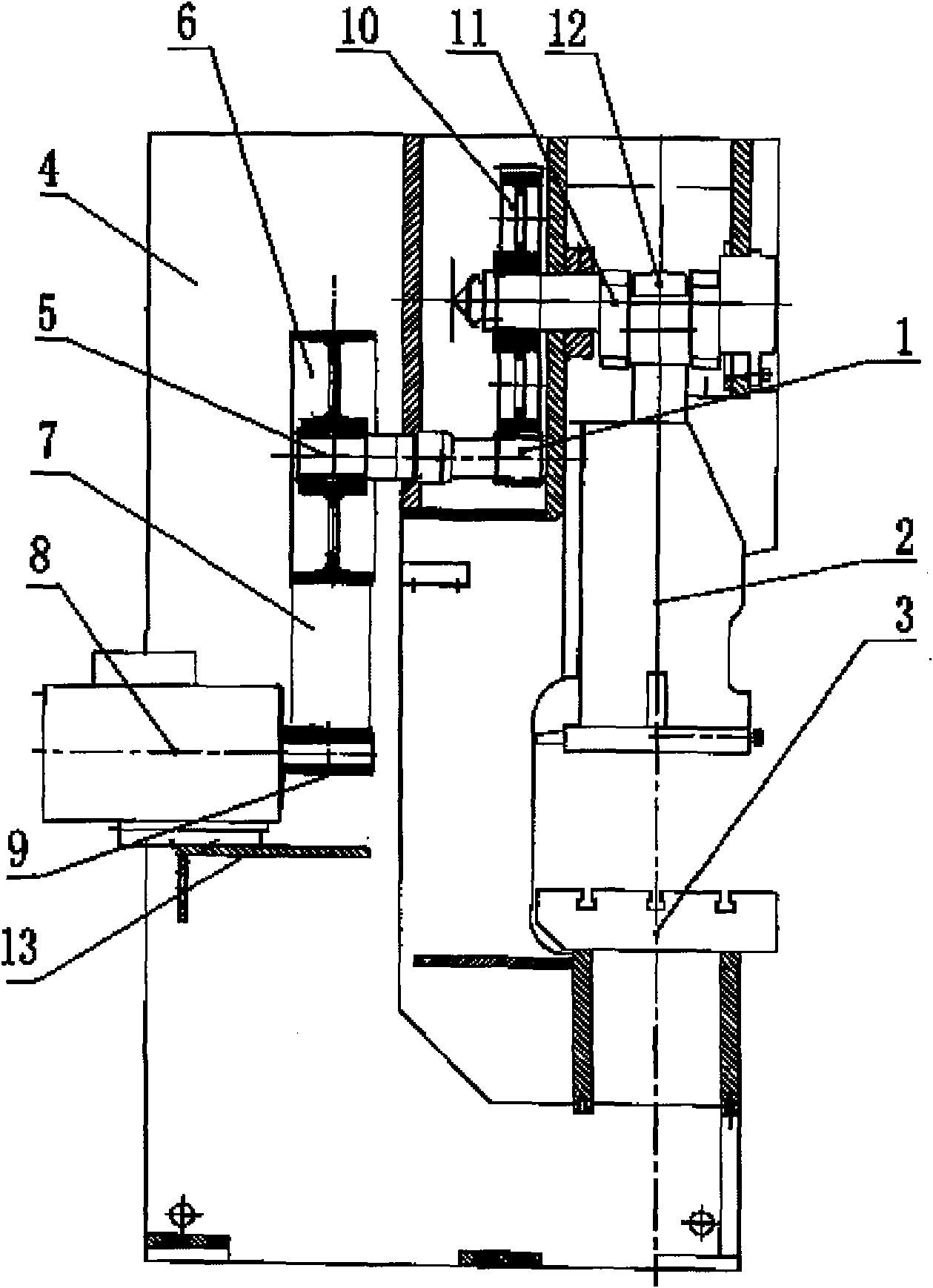
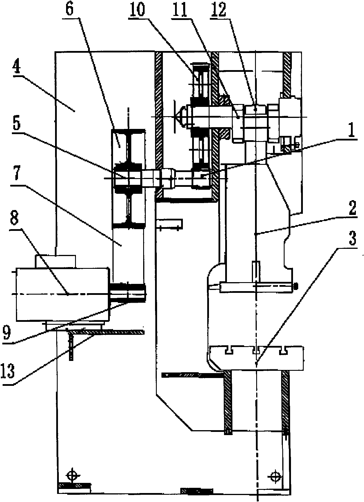
[0009] An automatic servo-driven press, comprising a slider (2) arranged above the workbench (3) of the press and connected to a connecting rod (12) that can slide vertically, and the other end of the connecting rod (12) is hinged on a crankshaft (11), the crankshaft (11) is connected with the driven gear (10) supported on the frame (4), the driven gear (10) is externally meshed with the driving gear (1), and the center of the driving gear (1) is fixed There is a gear shaft (5), the shaft end of the gear shaft (5) is provided with a driven wheel (6), and the rear opening position of the frame (4) is provided with a motor base (13), which is mounted on the motor base (13). There is a servo motor (8), the shaft end of the servo motor (8) is provided with a driving wheel (9), and the driving wheel (9) and the driven wheel (6) are connected through a synchronous belt (7). (8) rotate, and the torque is transmitted to the gear shaft (5) through the transmission of the driving wheel ...


PUM


Abstract

The invention relates to an automatic servo driving press machine, which comprises that: a sliding block is arranged above a worktable of the press machine, is connected with a connecting rod and can slide vertically; the other end of the connecting rod is hinged to a crankshaft; the crankshaft is connected with a driven gear supported on a frame; the driven gear is externally meshed with a driving gear; the center of the driving gear is fixed with a gear shaft; a shaft end of the gear shaft is provided with a driven wheel; a rear opening gear of the frame is provided with a motor base; a servo motor is arranged on the motor base; a shaft end of the servo motor is provided with a driving wheel; and the driving wheel and the driven wheel are connected by a synchronous belt. In working time, the servo motor rotates, a torque is transmitted to the gear shaft through the transmission of the driving wheel, the synchronous belt and the driven wheel, the gear shaft further drives the driving gear, the driven gear and the crankshaft to rotate, and the crankshaft drives the sliding block to move up and down when rotating. Relative sliding does not exist among the driving wheel, the synchronous belt and the driven wheel, so the position of the sliding block and an angle over which a rotor of the servo motor rotates correspond to each other.

Description

technical field [0001] The invention relates to a press, in particular to an automatic servo-driven press, which belongs to the technical field of press machinery. Background technique [0002] In the prior art, a vertically slidable slider is connected through a connecting rod above the working table of the press, and the other end of the connecting rod is hinged on a crankshaft, which is connected with a driven gear supported on the frame. The driving gear meshes with the driving gear. The gear shaft is fixed in the center of the driving gear. If the slider needs to slide, the transmission of the gear shaft needs to be controlled. The motor is installed on the frame of the traditional press, and the end of the motor shaft is equipped with a clutch. The pulley drives the gear shaft to rotate through the clutch. The clutch mostly adopts a rigid clutch or a pneumatic friction clutch. When working, the motor keeps rotating, and the slider is driven to move up and down or stop ...

Claims


Application Information

Patent Timeline
Patent Type & Authority Applications(China)
IPC IPC(8): B30B1/26
CPCB30B1/266
Inventor 杨茂召
Owner 杨茂召
Why Eureka
Try Eureka