Pneumatic and manual dual-purpose sampling valve

A technology of sampling valve and spool, which is applied in the direction of sampling device, etc., can solve the problems of affecting the sealing performance of sampling valve, damage of sealing plug sealing material, and the sampling valve is not equipped with left and right spin limit devices, so as to improve the safety of use and reliability, reduce maintenance costs, and ensure normal operation

Inactive Publication Date: 2010-09-22
浙江远安流体设备有限公司
View PDF8 Cites 7 Cited by
  • Summary
  • Abstract
  • Description
  • Claims
  • Application Information

AI Technical Summary

Problems solved by technology

[0006] For this reason, the technical problem to be solved by the present invention is that the sampling valve in the prior art is not provided with a left and right spin limiter, which makes it easy to cause the threaded connection between the valve core and the cylinder rod to slip after a long time of use. , it is easy to cause damage to the external sealing material of the s

Method used


Image

  • Pneumatic and manual dual-purpose sampling valve
  • Pneumatic and manual dual-purpose sampling valve
  • Pneumatic and manual dual-purpose sampling valve

Examples


Example Embodiment

[0033] Example 1

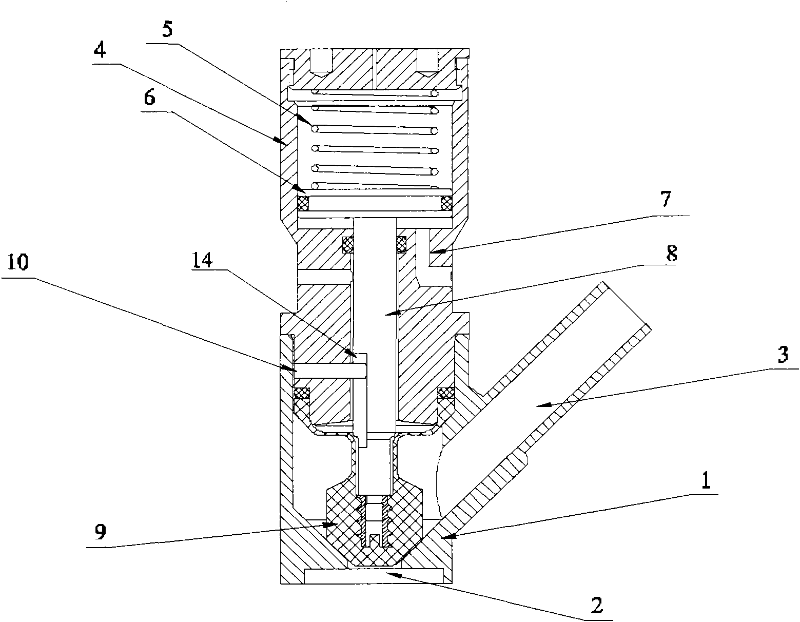
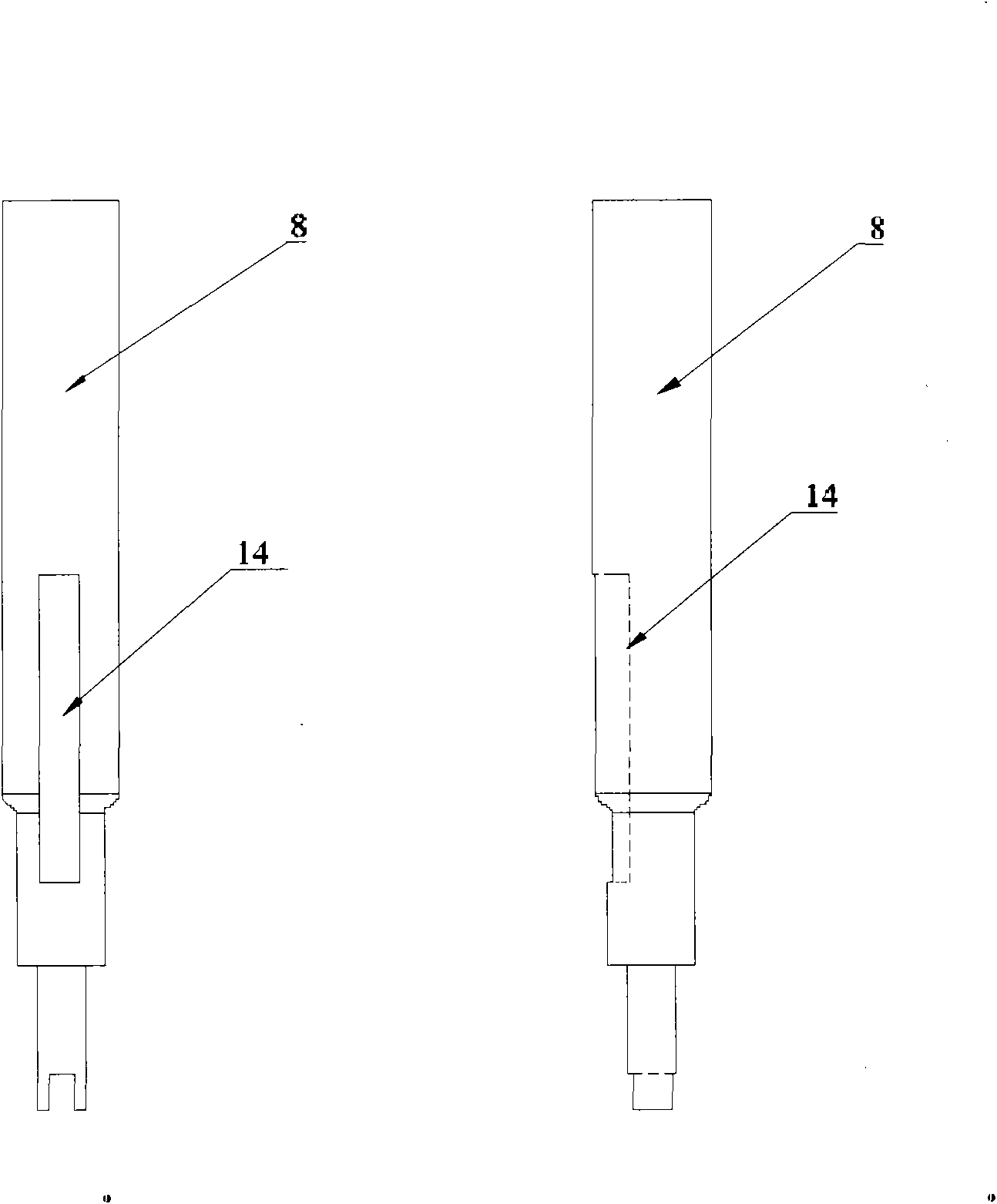
[0034] Such as figure 1 Shown is the sampling valve of the present invention. It can be seen from the figure that the sampling valve includes a cylinder 4, a piston control assembly located in the cylinder 4, and the piston control assembly consists of a piston 6 and the The biasing member 5 used to reset the piston 6 and the piston 6 is in contact with each other. In this embodiment, the biasing member 5 is a coil spring, and the number is one; the cylinder below the piston 6 4 is also provided with a power medium inlet and outlet 7, which is used to input or output power medium to provide a power source for the movement of the piston 6; in addition, below the cylinder 4 is the valve body 1, so The valve body 1 and the cylinder body 4 are connected in a sealed manner, and a feed port 2 and a feed port 3 are provided on the valve body. The sampling valve of the present invention also includes an important component, namely the valve core 8, which is arranged ...

Example Embodiment

[0039] Example 2

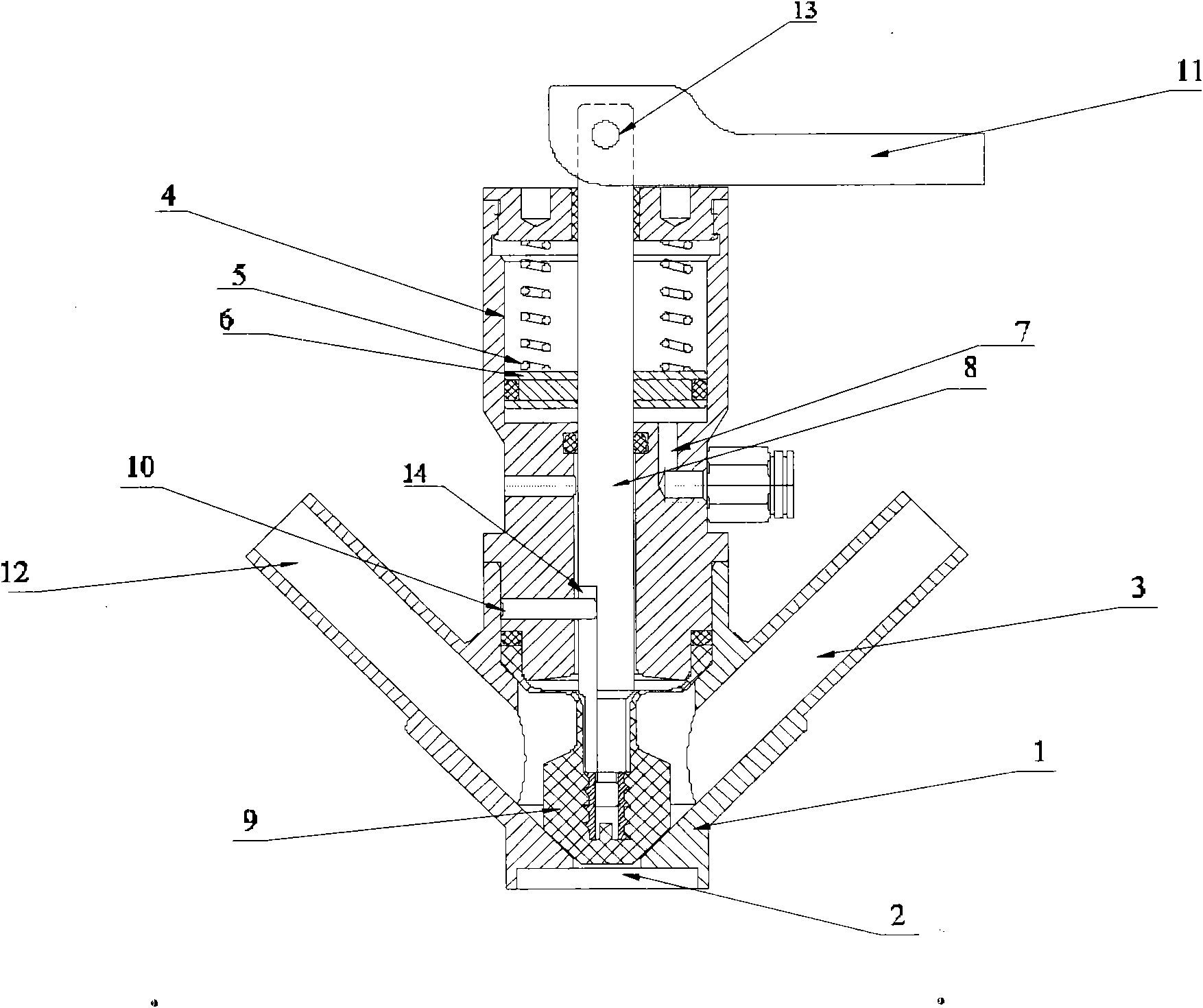
[0040] image 3 Another embodiment of the sampling valve of the present invention is given. In the sampling valve described in this embodiment, the upper end of the valve core 8 penetrates the piston 6 and extends beyond the top of the cylinder 4 to be opposite to the handle 11. The connection between the handle 11 and the valve core 8 is connected by a cam 13. The handle 11 can be moved upward along the connection point of the handle 11 and the valve core 8, so that the pneumatic setting can be used The components realize manual control sampling.

[0041] In this embodiment, a coil spring is provided in the cylinder 4 and at both ends of the valve core 8, see image 3 Shown.

[0042] In this embodiment, two discharge ports are provided on the valve body, one of the discharge ports 3 is used for sampling, and the other discharge port 12 can be used as a disinfection port.

[0043] When the sampling valve described in this embodiment is in use, by operating the ha...


PUM


Abstract

The invention provides a sampling valve comprising a valve body, a valve core, a cylinder body and a piston control assembly, wherein the valve core and the cylinder body are arranged in the valve body, the piston control assembly is arranged in the cylinder body, and the valve body is arranged below the cylinder body and is provided with a feed port and a discharge hole; the upper end of the valve core is connected with the piston control assembly, and the lower end of the valve core is connected and provided with a sealed drain plug which seals the feed port; the valve core is provided with a spacing groove along a valve core shaft; and the inner wall of the valve body is provided with a spacing chuck in sliding fit with the spacing groove. The sampling valve provided by the invention can realize all-around spacing to the valve core and the situation that the external sealing material of the sealed drain plug is damaged because of valve core spinning can not occurred. In addition, the sealed drain plug of the invention adopts the mode of combining ethylene propylene rubber with cheap inside and Teflon with expensive outside to ensure sealed drain plug performance and lower cost thereof at the same time.

Description

technical field [0001] The invention relates to a sampling valve, in particular to a sampling valve which can be used for liquid or gas sampling. Background technique [0002] The sampling valve is a valve used to collect materials for component analysis, and has been widely used in food, medicine and other industries. [0003] In the prior art, Chinese patent CN2864657Y discloses an automatic sampling valve, which includes a valve body and a valve core. The valve body includes a cylinder, a piston, a rear cover, a cylinder rod, and an inlet / outlet. The cylinder rod The outer end is connected to one end of the valve core, the inner end of the cylinder rod is fixedly connected to the end face of the piston, and the rear cover is connected to the end of the cylinder; in addition, the automatic sampling valve is also provided with a drive device and an automatic control device, the drive device can be optionally set as a cylinder, and the cylinder realizes pneumatic sampling t...

Claims


Application Information

Patent Timeline
IPC IPC(8): G01N1/10G01N1/22
Inventor 邵显安
Owner 浙江远安流体设备有限公司
Why Eureka
Try Eureka