Trapezoidal slow wave lines of coupling slot for traveling wave tube

A technology of coupling slots and traveling wave tubes, applied in the field of slow wave lines, can solve the problems of unstable operation and narrow bandwidth of high-order modes, and achieve the effect of solving unstable operation and increasing bandwidth

Inactive Publication Date: 2010-09-22
UNIV OF ELECTRONICS SCI & TECH OF CHINA
View PDF3 Cites 16 Cited by
  • Summary
  • Abstract
  • Description
  • Claims
  • Application Information

AI Technical Summary

Problems solved by technology

[0011] The purpose of the present invention is to overcome the shortcomings of narrow bandwidth and unstable operation of high-order modes in the existing coupling slot trapezoidal slow wave line, and provide a coupling slot trapezoidal slow wave line for traveling wave tubes. The present invention By adding photonic crystal strips to the coupling hole of the existing coupling slot trapezoidal slow wave line, unexpected technical effects have been achieved and the defects of the prior art have been overcome

Method used


Image

  • Trapezoidal slow wave lines of coupling slot for traveling wave tube
  • Trapezoidal slow wave lines of coupling slot for traveling wave tube
  • Trapezoidal slow wave lines of coupling slot for traveling wave tube

Examples


Embodiment 1

[0028] Embodiment 1: as Figure 5 , Figure 8 , Figure 9 and Figure 10shown. A coupling slot trapezoidal slow wave line for a traveling wave tube, consisting of multiple groups of rectangular metal plates 13 arranged periodically along the axial direction of the electron beam channel 8 of the traveling wave tube, the rectangular metal plates 13 are perpendicular to the axial direction, There is a circular hole in the center of the rectangular metal plate 13, and there are rectangular coupling grooves 14 at both ends of its narrow side. The rectangular metal plate 13 is wrapped by a metal shielding shell 5 extending in the axial direction, and the inside of the metal shielding shell 5 is A rectangle matching the size of the rectangular metal plate 13, with a photonic crystal strip 15 extending axially along the electron beam channel 8 in the coupling groove, the width of the photonic crystal strip 15 is the same as that of the rectangular coupling groove, and the thickness...

Embodiment 2

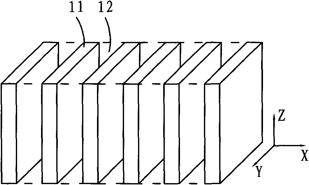
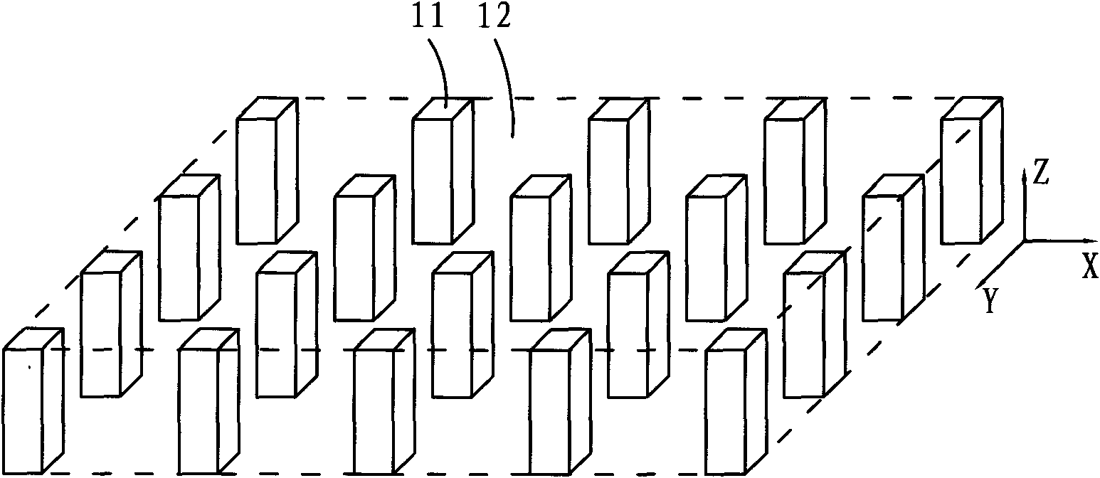
[0029] Embodiment 2: as Figure 5 , Figure 11 and Figure 12 shown. A coupling slot trapezoidal slow wave line for a traveling wave tube, consisting of multiple groups of rectangular metal plates 13 arranged periodically along the axial direction of the electron beam channel 8 of the traveling wave tube, the rectangular metal plates 13 are perpendicular to the axial direction, There is a circular hole in the center of the rectangular metal plate 13, and there are rectangular coupling grooves 14 at both ends of its narrow side. The rectangular metal plate 13 is wrapped by a metal shielding shell 5 extending in the axial direction, and the inside of the metal shielding shell 5 is A rectangle matching the size of the rectangular metal plate 13, each rectangular coupling groove 14 has two photonic crystal strips 15, the thickness of the photonic crystal strip 15 is the same as the rectangular coupling groove 14, and the width is less than half of the width of the rectangular co...


PUM


Abstract

The invention relates to trapezoidal slow wave lines of a coupling slot for a traveling wave tube. Multiple groups of rectangular metal plates are periodically arranged along the axial direction of an electron beam passage of the traveling wave tube; the rectangular metal plates are vertical to the axial direction; the centers of the rectangular metal plates are provided with round holes, and the two ends of narrow sides of the rectangular metal plates are provided with rectangular coupling slots; the rectangular metal plates are coated by axially extending metal shielding shells of which the insides have rectangular shapes matched with the sizes of the rectangular metal plates. The trapezoidal slow wave lines are characterized in that: at least one photonic crystal bar which extends along the axial direction of the electronic beam passage is arranged in the rectangular coupling slots. The trapezoidal slow wave lines have the advantage of overcoming the defects of narrow bandwidth and unstable higher-mode work existing in the conventional trapezoidal slow wave lines of the coupling slot.

Description

technical field [0001] The invention belongs to the technical field of microwave vacuum electronics, and in particular relates to slow wave lines of traveling wave tubes. Background technique [0002] Traveling wave tube is a broadband high-power microwave source device, which is widely used in radar communication and space satellite communication. Schematic diagram of the structure of the traveling wave tube figure 1 and figure 2 As shown, the traveling wave tube mainly includes: electron gun 1, slow wave line 2 (slow wave circuit), beamforming system 3, collector 4, metal shielding shell 5, input waveguide 6 and output waveguide 7. There is an electron beam channel 8 inside the slow wave line, the beamforming system 3 and the metal shielding shell 5 surround the outer circumference of the slow wave line in turn, the electron gun 1 and the collector 4 are respectively located at the two ends of the slow wave line, the input waveguide 6 and the output waveguide 7 are res...

Claims


Application Information

Patent Timeline
Patent Type & Authority Applications(China)
IPC IPC(8): H01J23/24
Inventor 宫玉彬殷海荣魏彦玉王文祥
Owner UNIV OF ELECTRONICS SCI & TECH OF CHINA
Why Eureka
Try Eureka