Feed source for microwave antenna and microwave antenna

A technology for microwave antennas and feeds, applied to antennas, antenna supports/mounting devices, electrical components, etc., can solve the problems of increased difficulty and cost in mass production, reduce shading loss, ensure consistency, and overcome technical problems the effect of prejudice

Inactive Publication Date: 2010-09-22
TONGYU COMM INC
View PDF16 Cites 12 Cited by
  • Summary
  • Abstract
  • Description
  • Claims
  • Application Information

AI Technical Summary

Problems solved by technology

[0006] However, the above two technical solutions have obvious technical prejudices, that is: both technical solutions consider "hollow medium cone" or "medium support cone" as a necessary technical feature, and the two solutions are respectively dedicated to improving the The material of the "hollow dielectric cone" and the local structure of the "dielectric support cone" to obtain better electrical performance
[0007] Due to the above-mentioned technical bias, the above two solutions put forward high requirements on the processing accuracy of the support structure, the dielectric constant, tangent loss angle, and humidity and heat stability of the support structure material, which increases the production cost. Make mass production more difficult

Method used


Image

  • Feed source for microwave antenna and microwave antenna
  • Feed source for microwave antenna and microwave antenna
  • Feed source for microwave antenna and microwave antenna

Examples


Embodiment Construction

[0042] The present invention will be described in further detail below in conjunction with the accompanying drawings and specific implementation examples, but it is not intended to limit the technical solution of the present invention.

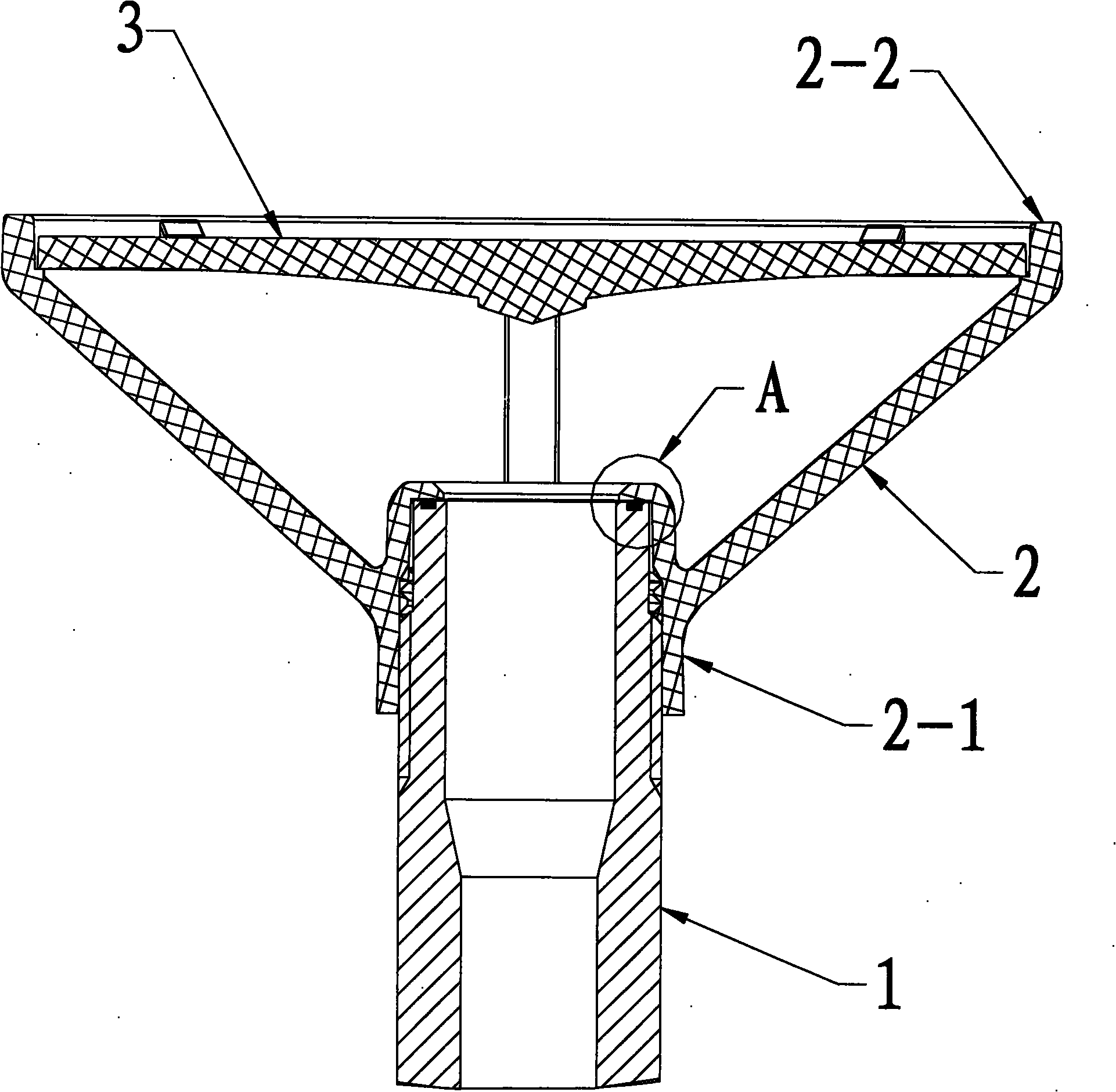
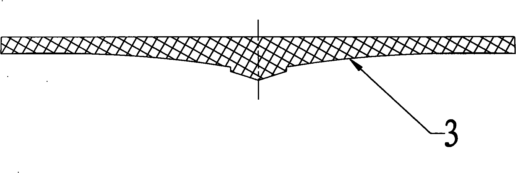
[0043] Such as figure 1 As shown, the microwave antenna feed source of the present invention is closely connected to the feed horn 1 through the first connection part 2-1 of the support frame 2, and connected to the secondary reflector 3 through the second connection part 2-2 of the support frame 2, and feeds The horn 1 and the secondary reflector 3 are on the same central axis.

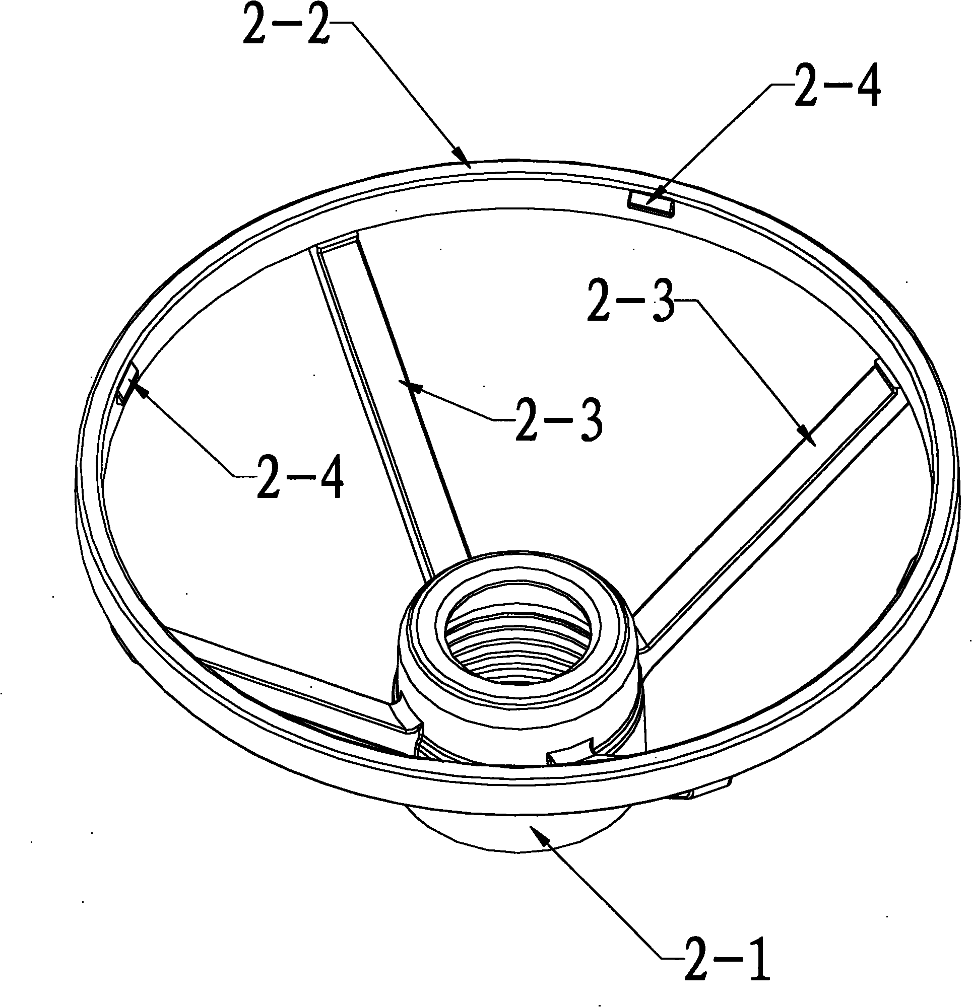
[0044] Such as figure 2 As shown, the support frame 2 of the present embodiment preferably has four support columns 2-3, and the four support columns 2-3 are connected and fixed to the first connection part 2-1 and the second connection part 2-2, and the second connection part 2 -2 is a ring that can just accommodate the sub-reflecting surface 3, and four evenly d...


PUM


Abstract

The invention discloses a feed source for a microwave antenna and the microwave antenna using the same, which comprises a feed horn, a supporting bracket and an auxiliary reflecting surface. The feed horn and the auxiliary reflecting surface are fixed to the same central axis by the supporting bracket; the supporting bracket comprises a first connecting part which is connected with the feed horn and a second part which is connected with the auxiliary reflecting surface; and the first connecting part and the second connecting part are fixedly connected with each other through at least one supporting post. An antenna radiation directional diagram which adopts the feed source meets the enveloping requirement of ETSI Class3 standard; the structure and the processing technique of the microwave antenna can ensure consistent performance well; and the microwave antenna has very low cost and is convenient for mass production.

Description

[technical field] [0001] The invention relates to the technical field of microwave antennas, and is particularly suitable for ultra-high-performance microwave antennas in the frequency range from 18GHz to 40Gz. [technical background] [0002] Microwave antenna is an important part of microwave relay communication system, and the feed source is the core of the whole microwave antenna. Designing a feed source with superior performance, reliable structure and low cost has always been expected by people. [0003] A standard Cassegrain antenna consists of three parts. The main reflector is a rotating paraboloid; the secondary reflector is a rotating hyperboloid, and it is fixed on the paraboloid with a support structure; the feed generally adopts various forms of horns. In transmission mode, the feed horn illuminates a sub-reflector, which reflects the energy of the spherical wave surrounding it to illuminate the primary reflector. The supporting structure blocks the radiation ...

Claims


Application Information

Patent Timeline
Patent Type & Authority Applications(China)
IPC IPC(8): H01Q19/18H01Q19/19H01Q1/12
Inventor 阳恩主冯晨波
Owner TONGYU COMM INC
Why Eureka
Try Eureka