
Structure for preventing continuous casting tundish from producing rotational flows

A continuous casting tundish and tundish technology, which is applied in the directions of casting melt containers, manufacturing tools, casting equipment, etc., can solve the problems that the improvement of the metal yield cannot be guaranteed by inclusions, and the loss of molten metal can be achieved. The effect of eliminating molten steel slag, low manufacturing cost and improving the quality of cast slabs

Inactive Publication Date: 2011-10-12
CHONGQING UNIV
View PDF0 Cites 0 Cited by
  • Summary
  • Abstract
  • Description
  • Claims
  • Application Information

AI Technical Summary

Problems solved by technology

A significant disadvantage of this method is at the cost of sacrificing the yield of molten metal
The second is to locally lower the bottom position near the nozzle, so that the critical height is partially reduced to this area, so as to achieve the dual purpose of reducing slag and improving the yield of molten metal (some researchers call it the lower storage method); however, using this method, a large number of modifications are required to the equipment itself, and at the same time, part of the molten metal will still be lost
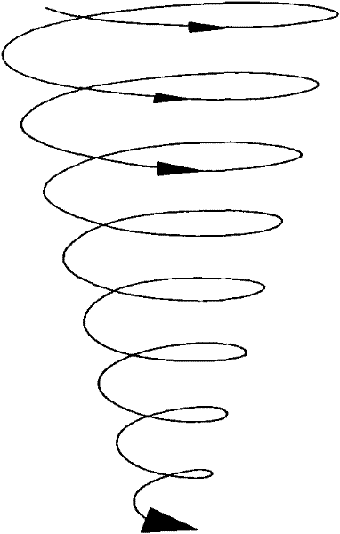
[0008] In short, most of the control of the tundish vortex in the abnormal pouring state in the process of controlling molten metal pouring focuses on improving the structure of the upper nozzle of the tundish. However, due to the complexity of the mechanism and form of vortex generation And diversity, so that in the abnormal pouring state of molten metal, the control of inclusions and the improvement of metal yield cannot be guaranteed

Method used


Image

  • Structure for preventing continuous casting tundish from producing rotational flows
  • Structure for preventing continuous casting tundish from producing rotational flows
  • Structure for preventing continuous casting tundish from producing rotational flows

Examples


Embodiment Construction

[0021] How to ensure that in the abnormal pouring state, by controlling the flow state of the molten metal near the upper nozzle of the tundish to control the generation of the vortex, and finally to control the slag entrapment of the molten metal and improve the yield of the molten metal, is the core of the patent of the present invention Purpose.

[0022] The present invention will be further described below in conjunction with accompanying drawing.

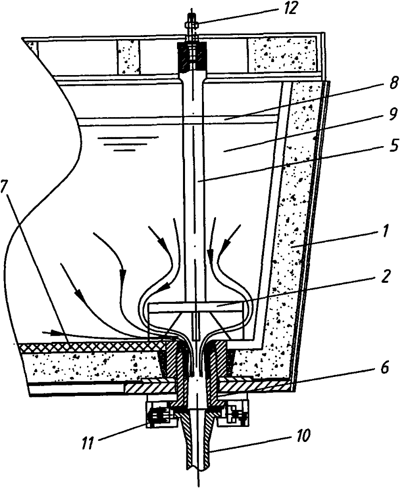
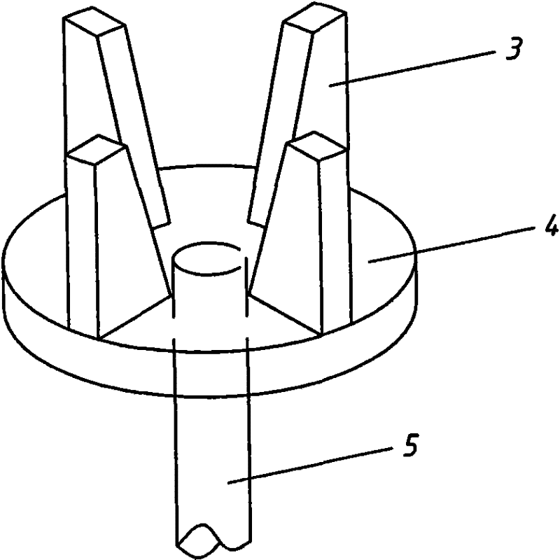
[0023] see figure 2 As can be seen from the figure, the structure of the present invention to prevent the swirl flow in the continuous casting tundish is provided with a swirl suppressor 2 made of refractory material that can be lifted in the tundish 1 . see also image 3 , the swirl suppressor 2 is mainly composed of a deflector 3, a disc 4 and a lifting rod 5 for lifting, the disc 4 is horizontally located directly above the upper nozzle 6 in the tundish, and the deflector 3 is several pieces ( The figure shows four piece...


PUM


Abstract

The invention discloses a structure for preventing a continuous casting tundish from producing rotational flows. The tundish is internally provided with a liftable rotational flow controller, and the rotational flow controller mainly comprises flow guide plates, a round disk and a lifting and pulling rod for lifting, wherein the round disk is horizontally positioned right above a water supply port in the tundish; a plurality of flow guide plates are symmetrically arranged on the lower surface of the round disk along the center and face to the center of the round disk; and the lifting and pulling rod is fixed in the center of the upper surface of the round disk. The round disk in the structure has the effect of fixing the flow guide plates on one hand and can cut off a passage generating the rotational flows on the other hand so as to compel molten metal to flow into the water supply port in a way of parallelism instead of perpendicularity to the bottom of the tundish. Therefore, the structure can fundamentally stop the generation of the rotational flows, which stops molten steel slag rolling and can obviously improve the casting blank quality under an abnormal pouring state, and meanwhile, the yield of the molten metal can also be obviously improved.

Description

technical field [0001] The invention relates to a liquid metal flow control structure, specifically a structure capable of preventing swirling flow in a continuous casting tundish, and belongs to the technical field of metal smelting. Background technique [0002] As a transitional device in the continuous casting process of molten metal, the tundish plays a very important role in the metallurgical process. Generally speaking, the main functions of the tundish generally have the following aspects: (1) reduce the static pressure of the molten metal and maintain a stable liquid level in the tundish; (2) promote the further floating of the inclusions in the molten metal to achieve the goal of purification Function; (3) diverting molten metal, for multi-strand continuous casting machines, distributing molten metal to each crystallizer through tundish; (4) storing molten metal, creating conditions for multi-furnace continuous casting. With the development of continuous casting m...

Claims


Application Information

Patent Timeline
Patent Type & Authority Patents(China)
IPC IPC(8): B22D41/00
Inventor 张健陈登福谢鑫朱开军
Owner CHONGQING UNIV
Learn More