

Electrohydraulic gyrator
A technology of electro-hydraulic gyrator and coupling, applied in the direction of fluid pressure actuating device, etc., can solve the problems of reducing welding area, easy oil leakage, difficult welding of electro-hydraulic gyrator, etc. The effect of the welding area
Inactive Publication Date: 2010-09-29
YANGZHOU ZHONGRUI TECH DEV
View PDF4 Cites 1 Cited by
- Summary
- Abstract
- Description
- Claims
- Application Information
AI Technical Summary
Problems solved by technology
[0005] The oil storage tank of the present invention is changed to a cylinder, and the cylinder itself does not need to be welded, only the connection with the peripheral parts needs to be welded. Compared with the old product, the welding area is reduced, and the welding difficulty and easy oil leakage of the electro-hydraulic gyrator are effectively solved. The problem
Method used
View moreImage
Smart ImageViewing Examples

Examples
Embodiment Construction
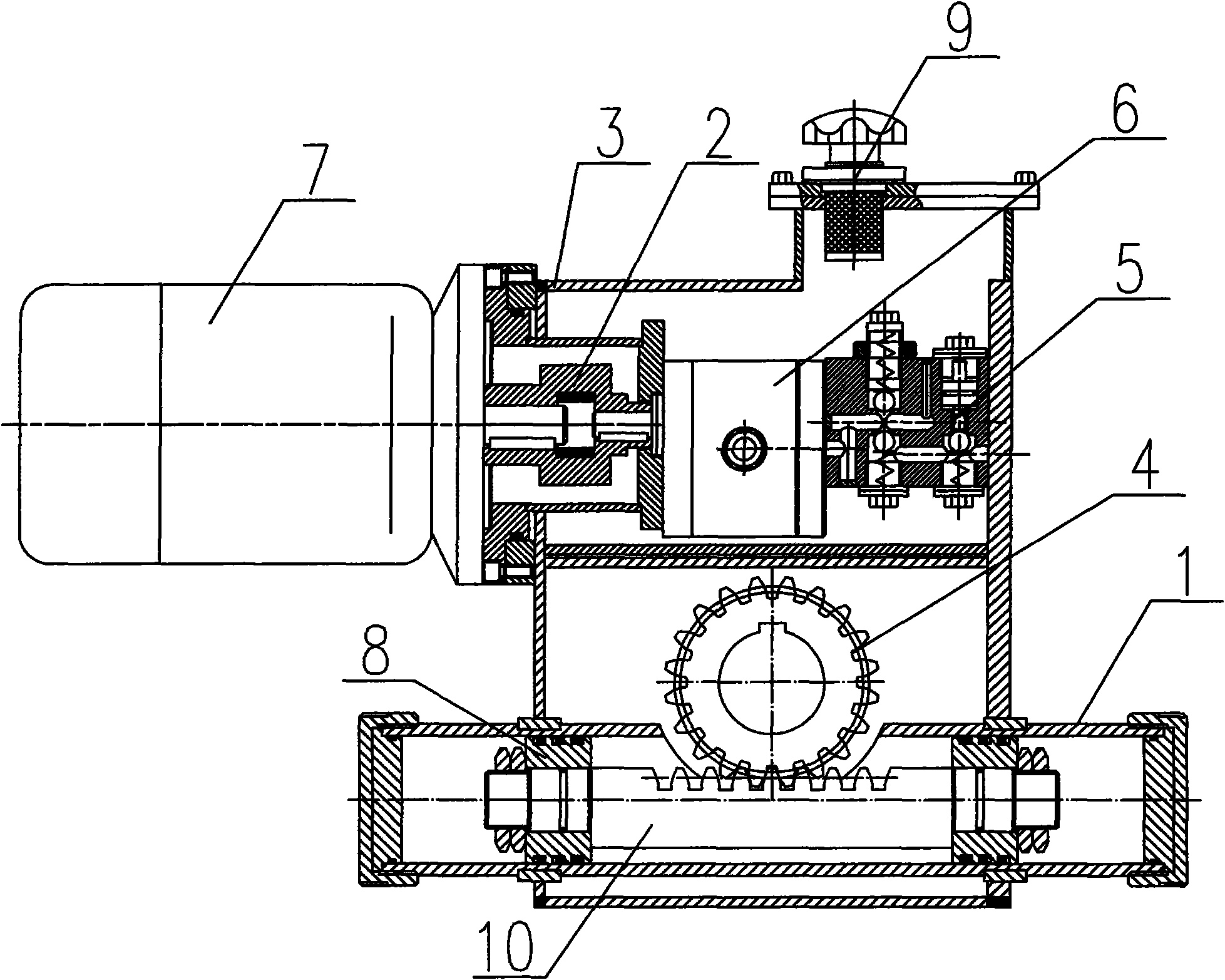
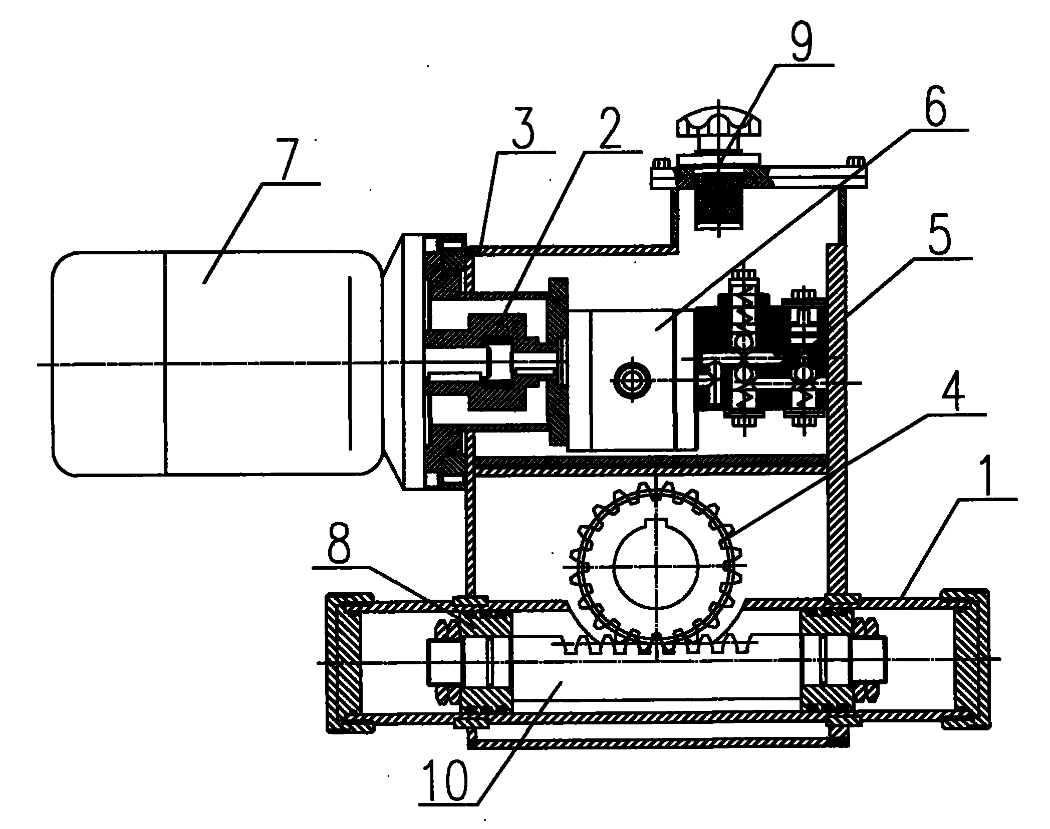
[0008] like figure 1 As shown, an electro-hydraulic gyrator includes a motor 7 and an oil storage tank 3. A gear pump 6 is arranged in the oil storage tank 3. The gear pump 6 is connected to the motor 7 through a coupling 2. The other end of the gear pump 6 is connected to an oil circuit for integration. Block 5, the top of oil storage tank 3 is provided with air cleaner 9, also comprises rotating gear 4, oil cylinder 1, piston 8, rack 10, and oil storage tank 3 is a cylinder.
Login to View More PUM
 Abstract
The invention, which belongs to the technical field of hydraulic control, relates to an electrohydraulic gyrator. The electrohydraulic gyrator comprises a motor and an oil storage tank, a gear pump is arranged in the oil storage tank, and is connected with the motor through a coupling, the other end of the gear pump is connected with a hydraulic manifold block, the upper part of the oil storage tank is provided with an air filter, the electrohydraulic gyrator also comprises a rotary gear, an oil cylinder, a piston and a rack, and the oil storage tank is a cylinder. Since the oil storage tank of the electrohydraulic gyrator is modified into the cylinder, the cylinder does not need to be welded, only the joints between the cylinder and the surrounding parts need to be welded, consequently, the welding area is reduced compared with the old product, and thereby the problems of the electrohydraulic gyrator, including difficult welding and easy oil leakage, are effectively solved.
Description
technical field [0001] The invention belongs to the technical field of hydraulic control, and in particular relates to an electro-hydraulic gyrator. Background technique [0002] The electro-hydraulic gyrator can complete the rotary motion in the range of 0-90° and 0-120°, and it is used in conjunction with butterfly valves, ball valves, dampers, etc. It is the actuator that replaces the electric head. The oil storage tank of the existing electro-hydraulic gyrator was originally The steel plate is welded into a square tube, the welding area is large, it is difficult, and it is easy to leak oil. Contents of the invention [0003] The purpose of the present invention is to provide an electro-hydraulic gyrator which is easy to weld and not easy to leak oil. [0004] The purpose of the present invention is achieved as follows: an electro-hydraulic gyrator, including a motor, an oil storage tank, a gear pump is arranged in the oil storage tank, the gear pump is connected to th...
Claims
Login to View More Application Information
Patent Timeline
 Patent Type & AuthorityApplications(China)
IPC IPC(8): F15B15/18
Inventor高方李贵荣孙全明
OwnerYANGZHOU ZHONGRUI TECH DEV