Heat recovery solution dehumidifying fresh air handling unit
A technology of solution dehumidification and fresh air unit, which is applied in space heating and ventilation, details of space heating and ventilation, energy recovery system for ventilation and heating, etc. It can solve the problem of solution concentration reduction and achieve the improvement of heat carrying capacity, Humidity increase, avoid regeneration target effect
- Summary
- Abstract
- Description
- Claims
- Application Information
AI Technical Summary
Problems solved by technology
Method used
Image

Examples
Embodiment 1
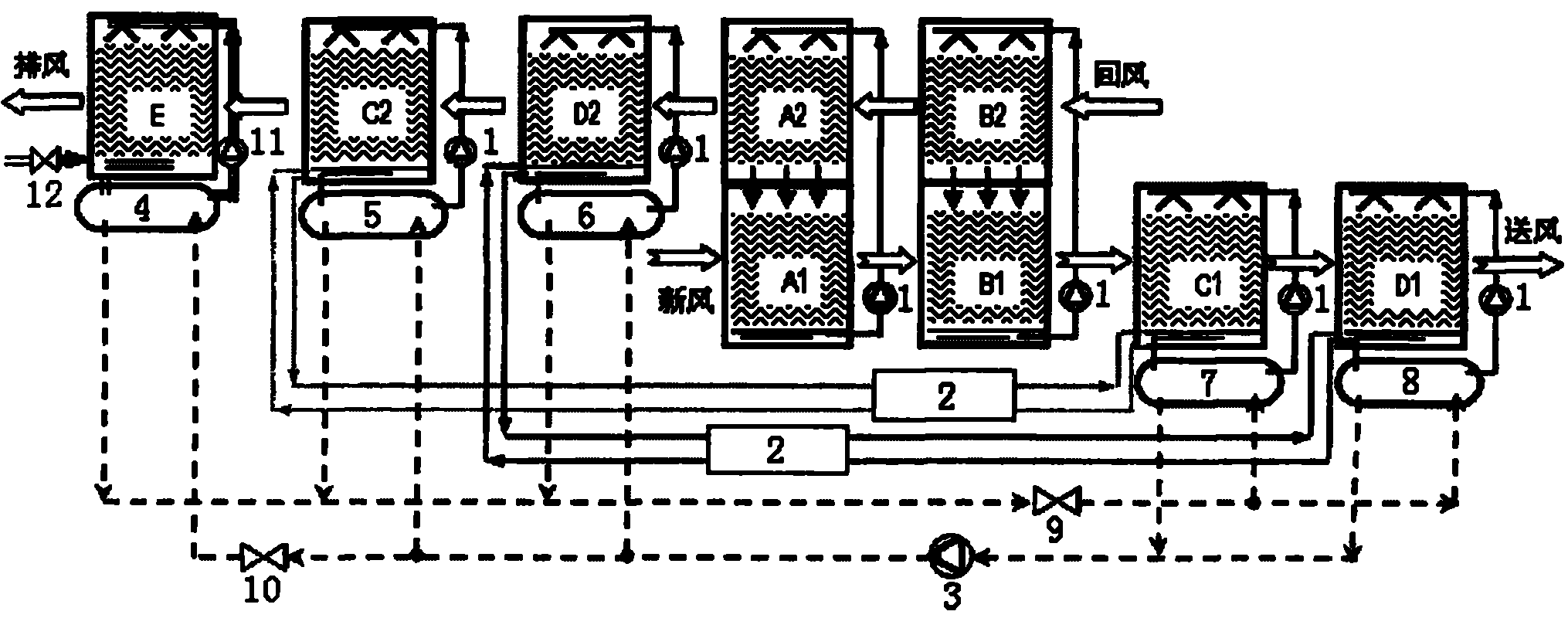
[0021] like figure 1 As shown, the fresh air unit of this embodiment includes a solution circulation system, a heat pump system and an evaporative cooling water system.
[0022]The solution circulation system includes two-stage total heat recovery modules A1-A2, B1-B2 composed of two gas-liquid direct contact spray modules connected in series, dehumidification modules C1, D1 and regeneration modules C2, D2. The two-stage total heat recovery modules A1-A2, B1-B2 are respectively connected with a solution circulation pump 1 to form a total heat recovery unit, and the gas-liquid directly contacts the spray modules A1, B1 and the dehumidification modules C1, D1 are arranged side by side to form a fresh air treatment channel ; Gas-liquid direct contact spray modules A2, B2 and regeneration modules C2, D2 are arranged side by side to form an indoor exhaust channel. The dehumidification module C1 is connected to the regeneration module C2, and the dehumidification module D1 is conne...
Embodiment 2
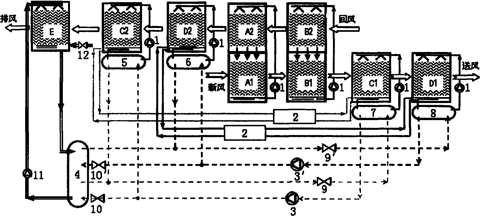
[0028] like figure 2 As shown, the difference between this embodiment and Embodiment 1 is that the heat pump system in the fresh air unit of this embodiment includes two heat pump circulation loops, the compressor 3, the condensers 4, 5, the evaporator 7 and the throttle valve 9 constitute a A heat pump circulation circuit, wherein the inlets of the condensers 4 and 5 are connected in parallel to the outlet of the compressor 3, the outlets of the condensers 4 and 5 are connected in parallel to the inlet of the throttle valve 9, and the inlet of the condenser 4 is provided with a solenoid valve 10 ; The inlet of the evaporator 7 is connected to the outlet of the throttle valve 9 in parallel, and the outlet of the evaporator 7 is connected to the inlet of the compressor 3 in parallel. Compressor 3 ', condenser 4, 6, evaporator 8 and throttling valve 9 ' constitute another heat pump cycle, wherein the inlets of condensers 4, 5 are all connected in parallel to the outlet of compr...
Embodiment 3
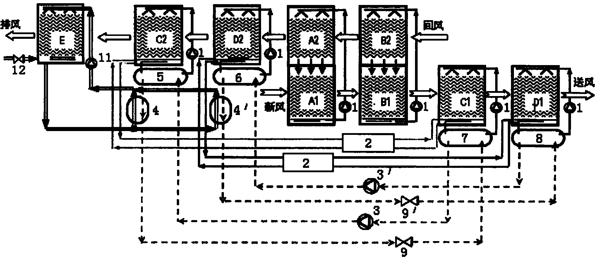
[0031] like image 3 As shown, the difference between this embodiment and Embodiment 1 is that the fresh air unit of this embodiment includes two sets of heat pump systems, and each set of heat pump systems consists of a compressor 3 (or 3′), a condenser 5 (or 6), a condenser 4 (or 4'), throttling valve 9 (or 9') and evaporator 7 (or 8) are sequentially connected to form an independent heat pump circulation loop, and the evaporative cooling module E exchanges heat with the condensers 4 and 4' respectively end in parallel.
[0032] In the above embodiments, the evaporative cooling module E can also be connected in series with the heat exchange ends of the condensers 4, 4' (not shown in the figure).
[0033] Although the structure of the fresh air unit in this embodiment is more complicated than that in Embodiment 1, because it has two sets of heat pump systems (that is, two independent heat pump circulation loops), its energy utilization efficiency is higher than that of the f...
PUM
 Abstract
Description
Claims
Application Information
 - R&D
- Intellectual Property
- Life Sciences
- Materials
- Tech Scout
- Unparalleled Data Quality
- Higher Quality Content
- 60% Fewer Hallucinations
Browse by: Latest US Patents, China's latest patents, Technical Efficacy Thesaurus, Application Domain, Technology Topic, Popular Technical Reports.
© 2025 PatSnap. All rights reserved.Legal|Privacy policy|Modern Slavery Act Transparency Statement|Sitemap|About US| Contact US: help@patsnap.com