Check patentability & draft patents in minutes with Patsnap Eureka AI!

Bevel stacked triangular iron core structure

A triangular iron and triangle technology, applied in the direction of transformer/inductor core, inductor/transformer/magnet manufacturing, electrical components, etc., can solve the problems of large no-load current, low core efficiency and high machining accuracy, and achieve no-load current. and no-load loss reduction, cost saving, less consumables

Inactive Publication Date: 2010-09-29
HAINAN JINPAN INTELLIGENCE TECH CO LTD
View PDF2 Cites 5 Cited by
  • Summary
  • Abstract
  • Description
  • Claims
  • Application Information

AI Technical Summary

Problems solved by technology

[0002] The traditional triangular three-dimensional iron core and the conventional planar iron core, the disadvantage of the conventional triangular three-dimensional iron core is that the length of the processed pieces is not equal, the processing accuracy is high, the processing is difficult, and the seam is large
The disadvantages of planar iron core mainly reflect that there are many materials, large loss and large no-load current
The iron core structure of the three-phase transformer is mostly made of stacked or rolled silicon steel sheets arranged in a plane. There are some shortcomings in the iron core of the stacked structure of the silicon steel sheets arranged in a plane: the utilization rate of the silicon steel sheets is low, there are many consumables, and the volume is large; Although the three-dimensional iron core that has been popular for several years has the advantages of low no-load loss and low noise, it still has strict requirements on the quality of silicon steel sheets, low utilization rate of silicon steel sheet materials, low efficiency of iron core manufacturing, and the need to invest in special equipment. , Coil winding is inconvenient and other deficiencies

Method used


Image

  • Bevel stacked triangular iron core structure
  • Bevel stacked triangular iron core structure
  • Bevel stacked triangular iron core structure

Examples


Embodiment Construction

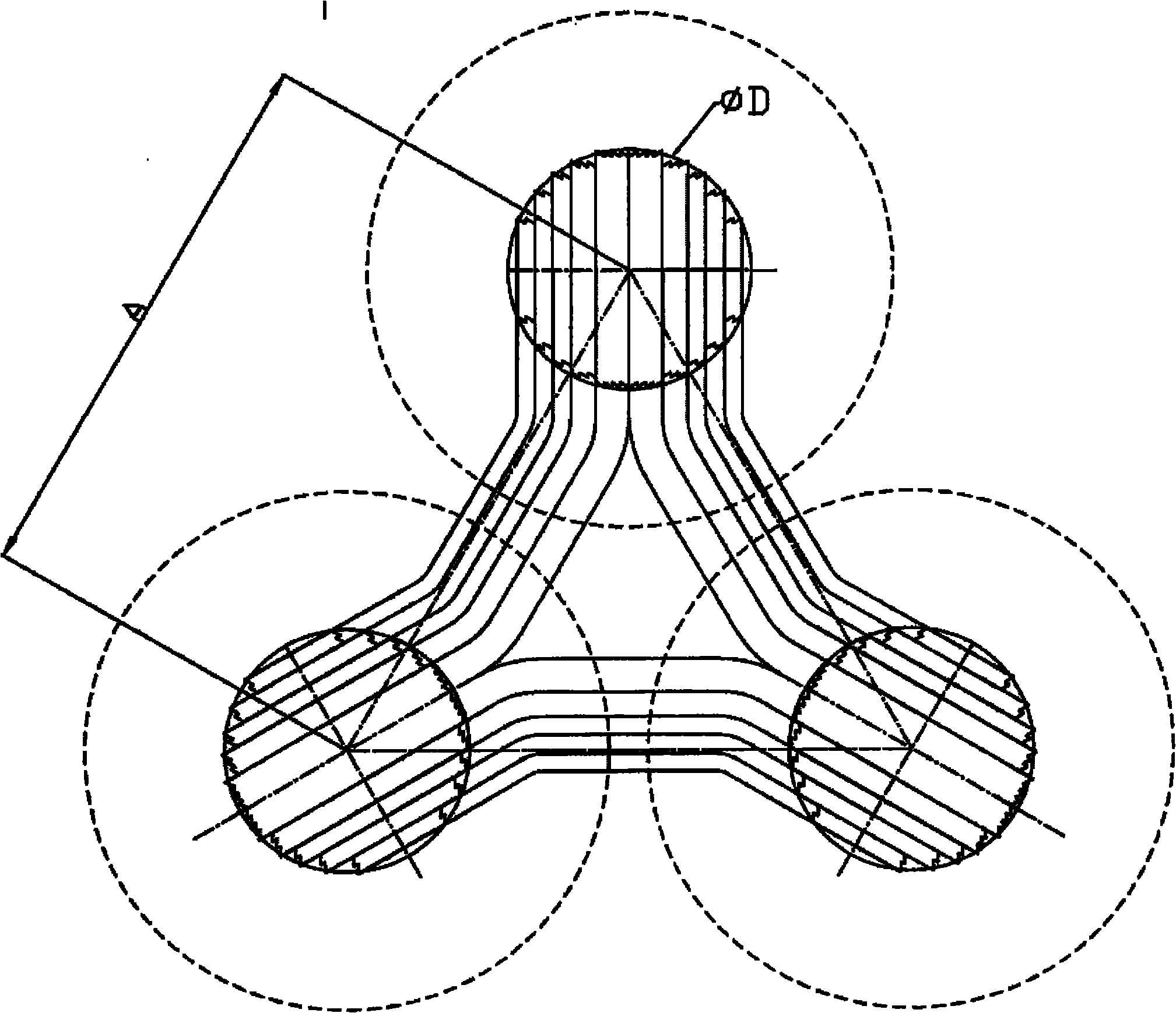
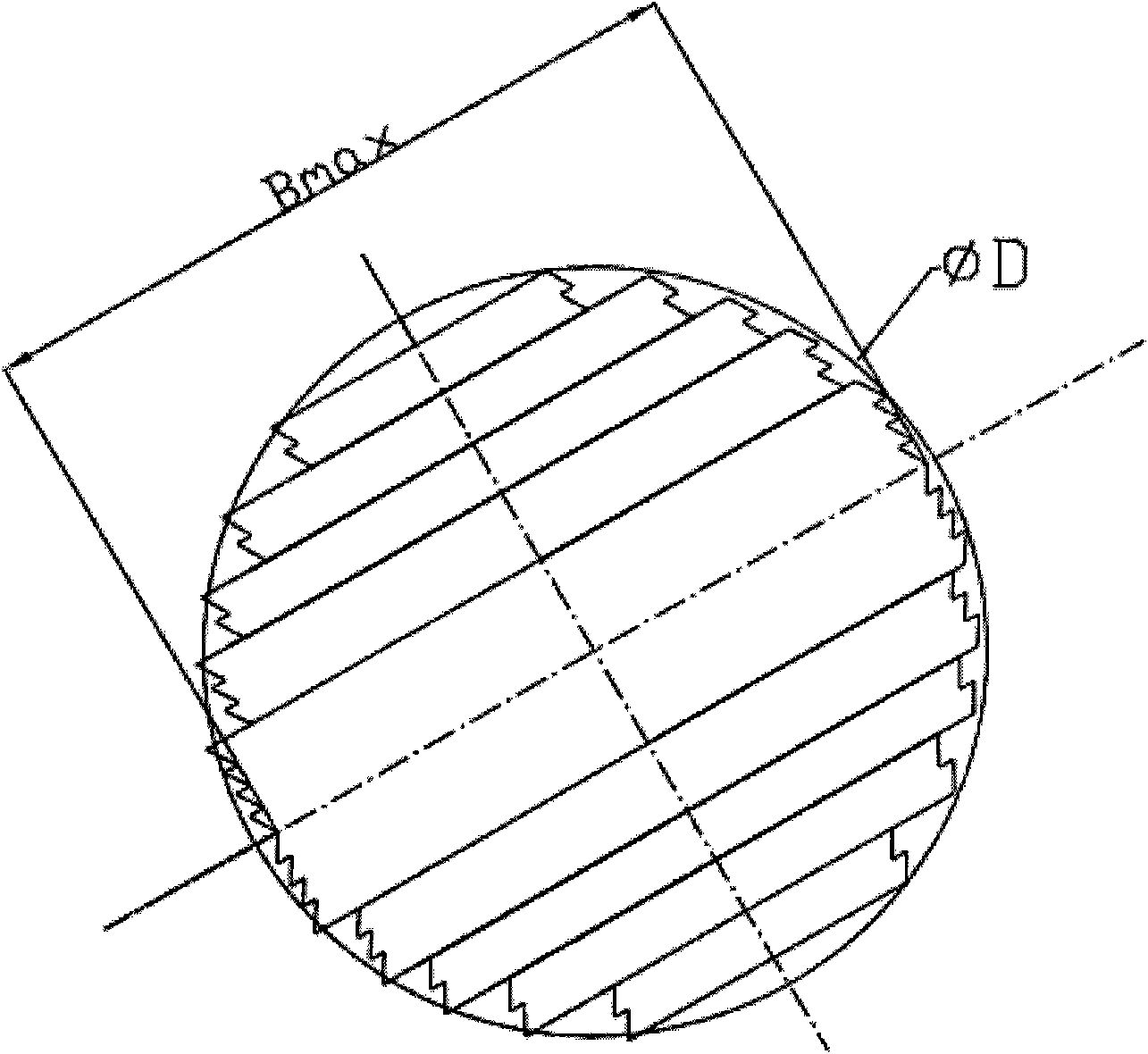
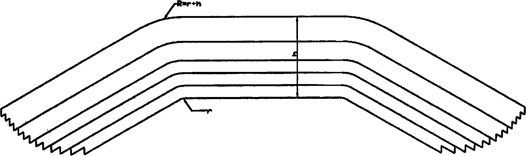
[0009] Firstly, according to the calculation method of planar three-phase transformer or reactor core, calculate the cross-sectional area (D) of the iron core column (D), the window height and the width of the multi-stage iron core to make the stacked triangular iron core structure transformer or reactor . The three-phase iron core is composed of three iron core columns with approximately circular cross-section shapes and six upper and lower yokes with approximately semicircular cross-sectional shapes and two ends folded into obtuse angles. The cross-sectional area of ​​each yoke is equal to the cross-sectional area of ​​the column half of. The slice length of each yoke piece is composed of the length of the arc and the length of the straight line. The length of the arc is calculated according to the radius of the mold arc (r) and the thickness of the laminations (h) at each level. The length of the straight line is calculated by the distance between phases (A) and Slice widt...


PUM


Abstract

The invention relates to a bevel stacked triangular iron core structure, which belongs to the technical field of power transmission and distribution equipment and is applicable to a transformer or a reactor. The bevel stacked triangular iron core structure is characterized in that three iron core columns in a triangle and with approximately circular sectional areas are connected through three upper yoke insertion sheets and three lower yoke insertion sheets with approximately semicircular sectional areas and folded obtuse angles at two ends to form a closed three-dimensional triangular magnetic circuit; a transformer iron core with the structure has the advantages of completely symmetrical three-phase magnetic circuits, shorter magnetic circuits, smaller volume and lower material consumption, more silicon steel sheet material saving and great reduction in no-load current and no-load loss, and has an efficient, energy-saving and environment-friendly transformer iron core structure; and the structure does not need to increase new equipment, can be realized by using the processing equipment for a conventional planar stacked iron core, and overcomes the defects of high equipment investment, coil winding inconvenience, waste of silicon steel sheets and the like of a triangular coiled iron core.

Description

Technical field [0001] The invention relates to a corner-stacked triangular iron core structure, which belongs to the technical field of power transmission and distribution equipment and is suitable for transformers or reactors. Background technique [0002] The traditional triangular three-dimensional iron core and the conventional planar iron core, the disadvantages of the conventional triangular three-dimensional iron core are that the lengths of the processed pieces are not equal, the processing accuracy is high, the processing is difficult, and the seams are large. The disadvantages of the planar iron core mainly reflect that there are many materials, large loss, and large no-load current. The iron core structure of the three-phase transformer is mostly made of stacked or rolled silicon steel sheets arranged in a plane. There are some shortcomings in the iron core of the stacked structure of the silicon steel sheets arranged in a plane: the utilization rate of the silic...

Claims


Application Information

Patent Timeline
IPC IPC(8): H01F27/26H01F27/24H01F41/02
Inventor 陈伟雷涌张绪俊冉启辉郭勇
Owner HAINAN JINPAN INTELLIGENCE TECH CO LTD
Features
  • R&D
  • Intellectual Property
  • Life Sciences
  • Materials
  • Tech Scout
  • Unparalleled Data Quality
  • Higher Quality Content
  • 60% Fewer Hallucinations
Learn More