Super-high pressure mercury lamp for projector with high light utilization rate

A projector, ultra-high voltage technology, applied in the direction of optics, instruments, gas discharge lamp parts, etc., can solve the problem that the cathode spot is not located on the parabolic reflector or elliptical reflector, the light utilization rate is low, and the liquid crystal panel of the projector is limited. issues such as the process of miniaturization, to achieve the effects of increasing light utilization, meeting miniaturization, and saving energy

Inactive Publication Date: 2010-09-29
王国华
View PDF1 Cites 0 Cited by
  • Summary
  • Abstract
  • Description
  • Claims
  • Application Information

AI Technical Summary

Problems solved by technology

When the existing ultra-high pressure mercury lamp is used in a small liquid crystal panel projector, only the center of the arc is located at the focal point of the parabolic reflector or elliptical reflector, and its light can be utilized, while the cathode spot is not located at the focus of the parabolic reflector or elliptical reflector. At the focal point, its light cannot be utilized, so its light utilization rate is low, and it cannot meet the requirements of high-brightness point light sources for projectors
However, limited by the manufacturing process, pressure resistance, and heat resistance of the arc tube and electrodes, it is difficult to further increase the total luminous intensity of the ultra-high pressure mercury lamp, thus limiting the miniaturization process of the LCD panel of the projector

Method used


Image

  • Super-high pressure mercury lamp for projector with high light utilization rate
  • Super-high pressure mercury lamp for projector with high light utilization rate
  • Super-high pressure mercury lamp for projector with high light utilization rate

Examples


Embodiment 1

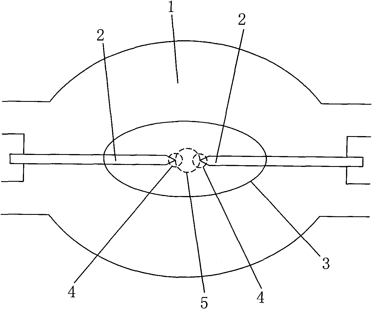
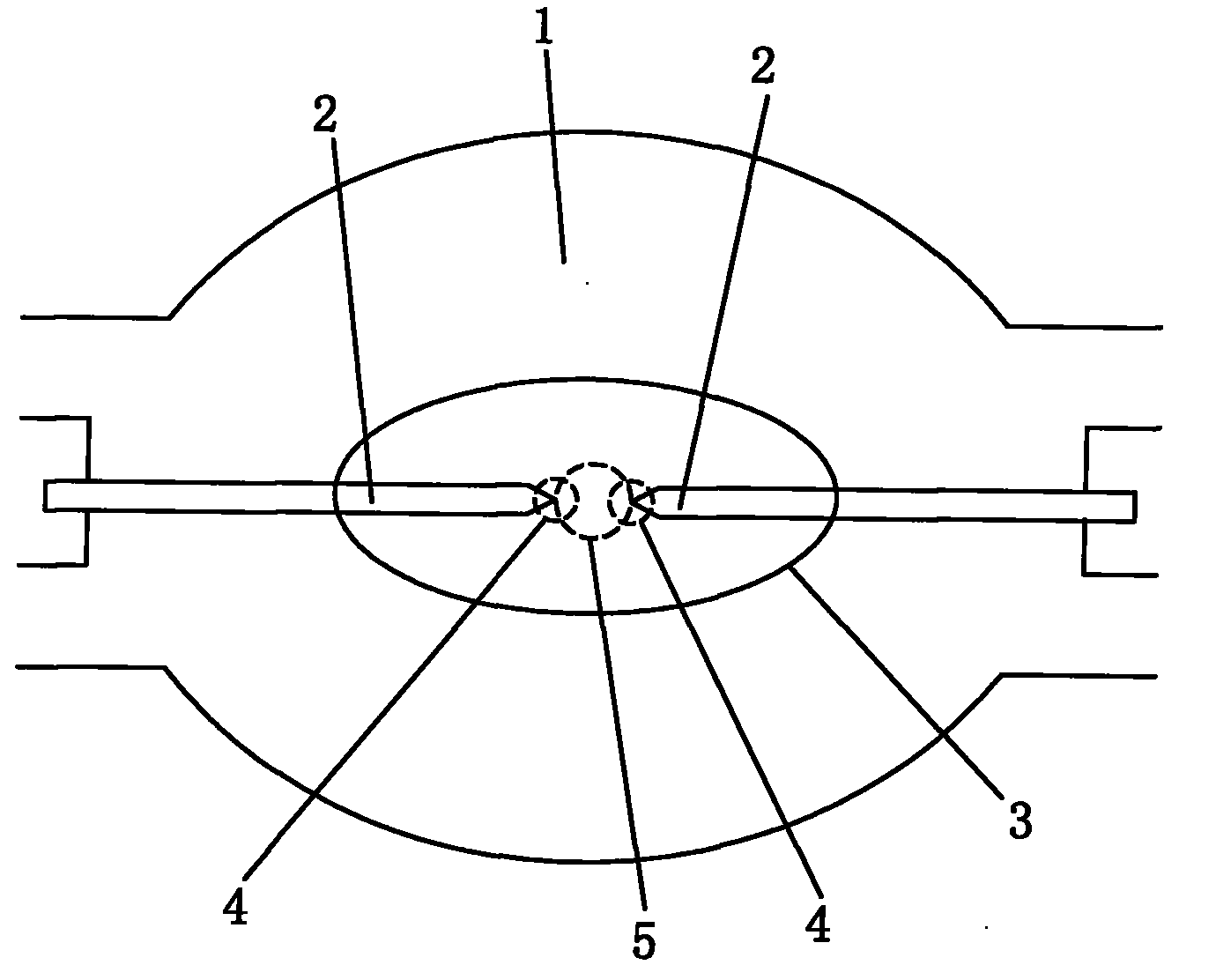
[0011] figure 1 It is shown that an ultra-high pressure mercury lamp for projectors with high light utilization efficiency in this example includes an arc tube 1 and two electrodes 2 arranged in a discharge space 3 of the arc tube 1 and placed opposite to each other. The distance between the two electrodes 2 is the distance at which the arc center 5 and the cathode spot 4 intersect or overlap when the discharge emits light.

[0012] figure 1 It is also shown that the ultra-high pressure mercury lamp of this example is an AC ultra-high pressure mercury lamp, the two electrodes 2 of the AC ultra-high pressure mercury lamp are the same, and there are two cathode spots 4, that is, the extreme tips of the two electrodes 2 take turns to withstand the ultra-high pressure. The bombardment of high-voltage electrons forms respective high-brightness spots near the ends of the two electrodes 2 .

[0013] The distance between the two electrodes of the existing AC ultra-high pressure merc...

Embodiment 2

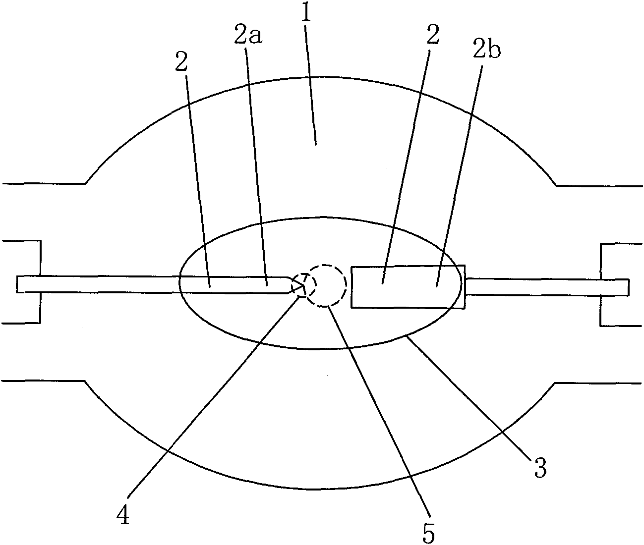
[0015] figure 2 It is shown that a specific embodiment of the present invention is: an ultra-high pressure mercury lamp for projectors with high light utilization rate, comprising an arc tube 1 and two electrodes 2 arranged oppositely in a discharge space 3 of the arc tube 1 . The distance between the two electrodes 2 is the distance at which the arc center 5 and the cathode spot 4 intersect or overlap when the discharge emits light.

[0016] figure 2 It is also shown that the ultra-high pressure mercury lamp in this example is a DC ultra-high pressure mercury lamp, and one of the two electrodes 2 is a cathode 2 a and the other is an anode 2 b. There is only one cathode spot 4 , which is bombarded by ultra-high voltage electrons at the very tip of the cathode 2 a in the electrode 2 , and a high-brightness spot is formed near the end of the cathode 2 a .

[0017] The distance between the two electrodes 2 (cathode 2a and anode 2b) of the existing DC ultra-high pressure merc...


PUM


Abstract

The invention relates to a super-high pressure mercury lamp for a projector with high light utilization rate, which comprises an electric arc tube (1) and two electrodes (2) which are arranged in a discharge space (3) of the electric arc tube (1) oppositely; the mercury lamp is characterized in that the distance between the two electrodes (2) is the distance which makes an electric arc center (5) is crossed or overlapped with a cathode spot (4) when in discharge and light emitting. The super-high pressure mercury lamp for the projector has high light utilization rate, and can greatly improve the intensity of the light emitted by an LCD panel of the projector under the circumstance of not improving the overall light emitting intensity of the lamp.

Description

technical field [0001] The invention relates to an AC or DC ultra-high pressure mercury lamp for projectors. Background technique [0002] The projection light source used by the projector is an AC or DC ultra-high pressure mercury lamp. The ultra-high pressure mercury lamp projects light onto a controlled liquid crystal panel, and projects various graphics and patterns onto the screen through the controlled liquid crystal panel. At present, more and more projectors use small liquid crystal panels. The luminous center (arc center) of the ultra-high pressure mercury lamp of this projector is located at the focal point of the parabolic emitting mirror or elliptical reflector, and only the light emitted at the focal point , can be projected onto the LCD panel and be effectively used. The rest of the light emitted by the ultra-high pressure mercury lamp will be scattered and cannot be projected on the liquid crystal panel, so it cannot be used. With the increasing miniaturizat...

Claims


Application Information

Patent Timeline
Patent Type & Authority Applications(China)
IPC IPC(8): H01J61/04G03B21/20
Inventor 王国华
Owner 王国华
Why Eureka
Try Eureka