
Method for processing signals between analog exciter and power amplifier and interface circuit

A signal processing and exciter technology, applied in the field of transmitters, can solve problems such as the system not working properly, and achieve the effects of simple structure, improved economic benefits, and reduced manufacturing costs

Active Publication Date: 2010-09-29
BEIJING BBEF SCI & TECH
View PDF1 Cites 8 Cited by
  • Summary
  • Abstract
  • Description
  • Claims
  • Application Information

AI Technical Summary

Problems solved by technology

Exceeding the hardware speed limit of the mixer will cause the system to fail to work normally, and it will be more serious with the increase of the number of split layers n

Method used


Image

  • Method for processing signals between analog exciter and power amplifier and interface circuit
  • Method for processing signals between analog exciter and power amplifier and interface circuit
  • Method for processing signals between analog exciter and power amplifier and interface circuit

Examples


Embodiment 1

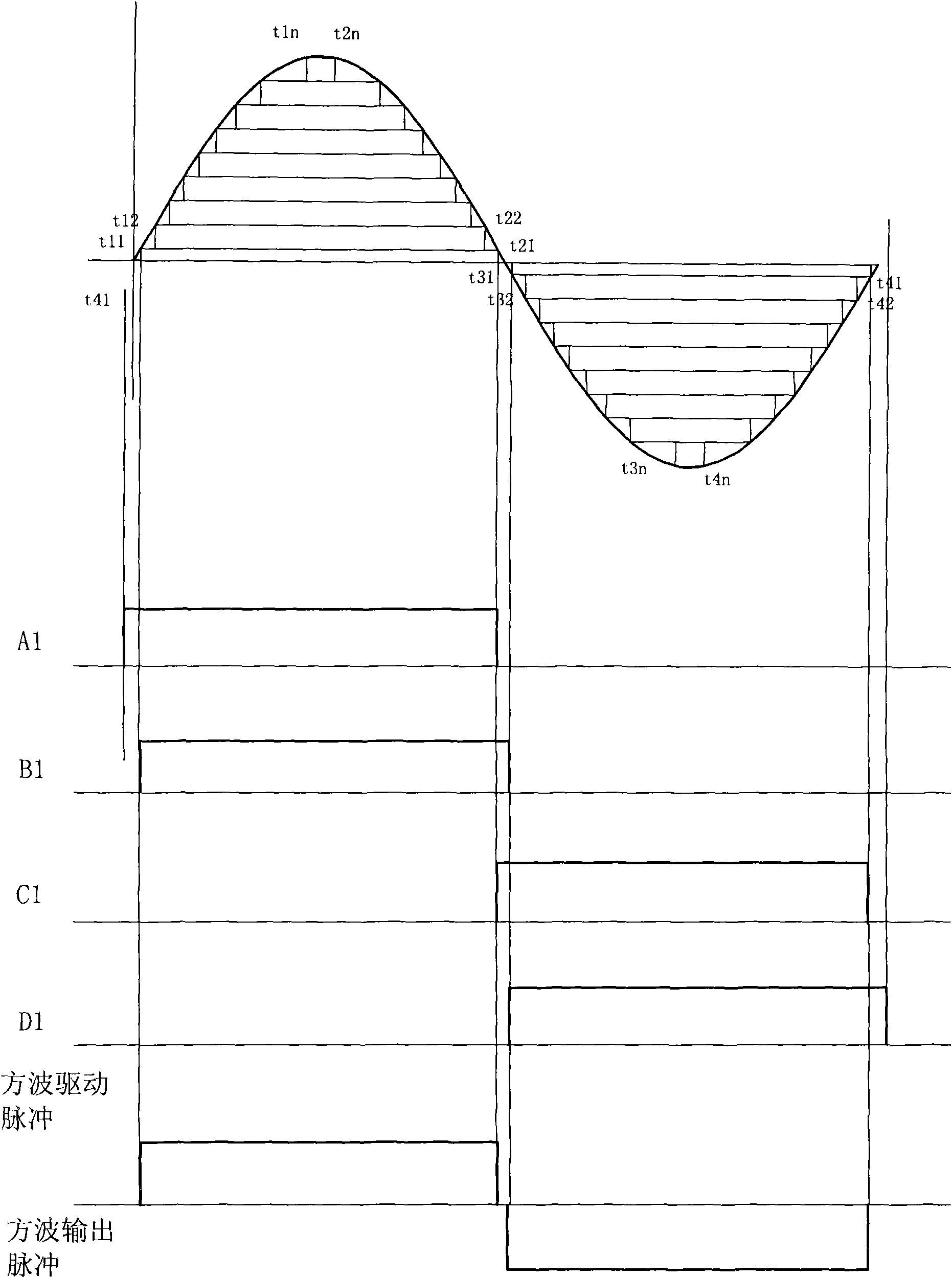
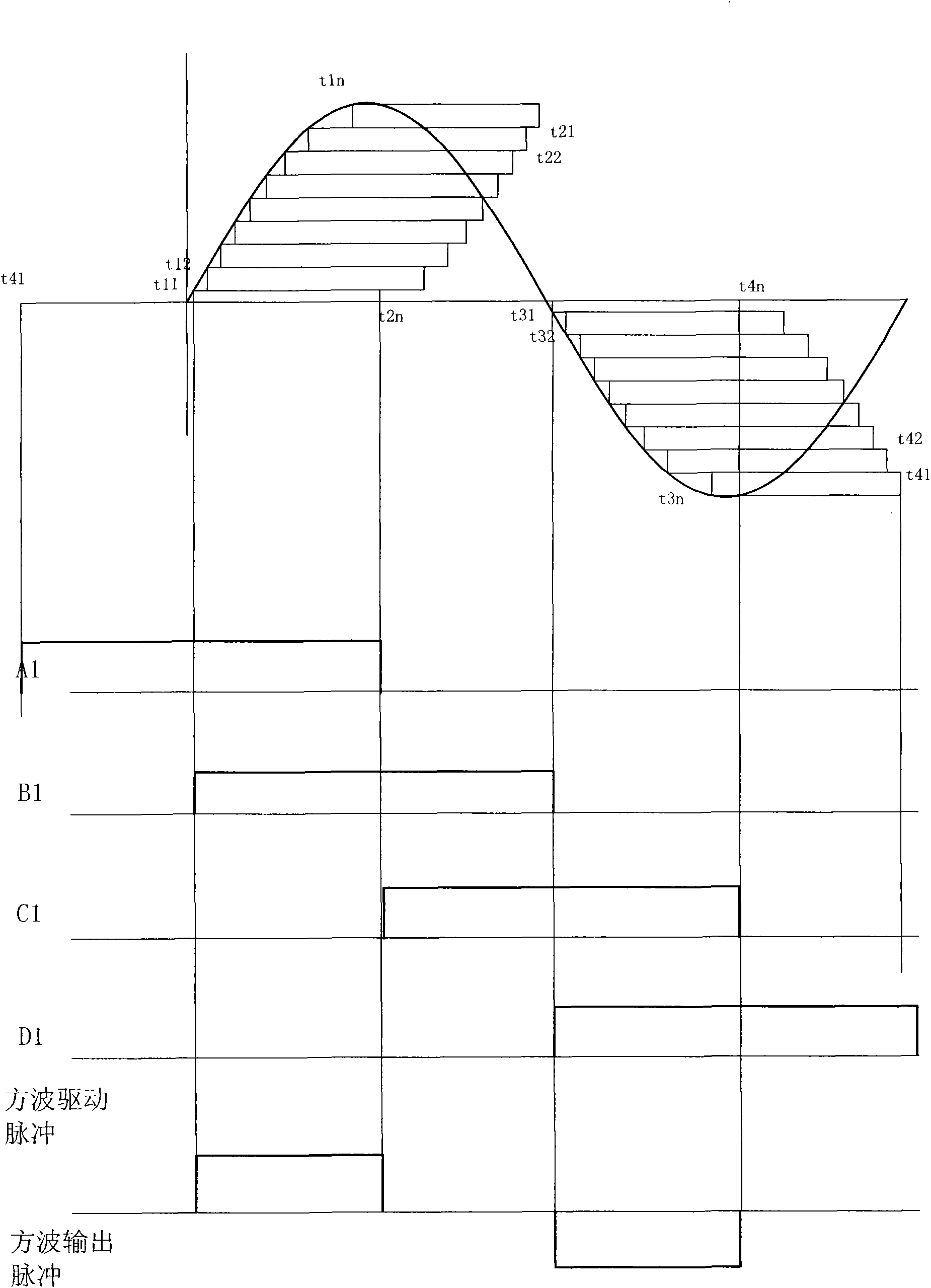
[0070] Such as Figure 10 , Figure 11 As shown, the interface circuit between the analog exciter and the switching power amplifier provided by the present invention includes an amplitude comparison timer and a drive pulse generator, the amplitude comparison timer has 2n paths, and the drive pulse generator has 4n , wherein said 2n-way amplitude comparison timers include n-way positive half-wave amplitude comparison timers and n-way negative half-wave amplitude comparison timers (see Figure 11 ), each path amplitude comparison timer includes a comparator, a differential circuit, and a first delayer, and the comparator has two input terminals, one input terminal is connected to an analog exciter, and the other input terminal is connected to a reference voltage generator, and the analog The signal is compared with the reference voltage by the comparator, the positive half-wave outputs high level, and the negative half-wave outputs low level; each comparator is connected with a...

Embodiment 2

[0073] The present invention also provides another interface circuit between the analog exciter and the switching power amplifier. The difference from Embodiment 1 is that the amplitude comparison timer is different, and its structure is as follows: Figure 12 As shown, it includes 2n-way amplitude comparison timers and 4n drive pulse generators, wherein the 2n-way amplitude comparison timers include n-way positive half-wave amplitude comparison timers and n-way negative half-wave amplitude comparison timers, each The amplitude comparison timer includes a comparator, first and second differential circuits, and first and second delayers. The comparator has two input terminals, one input terminal is connected to an analog exciter, and the other input terminal is connected to a reference voltage Generator, the output end is divided into two circuits, one is connected to the first differential circuit, the first differential circuit is connected to the second delayer, the other is ...


PUM


Abstract

The invention relates to a transmitter, in particular relating to a method for processing signals between an analog exciter and a power amplifier used for a long wave / super long wave transmitter and an interface circuit thereof. The method comprises the following steps: dividing sine voltage signals of the analog exciter into 2n numbered constant amplitude square-wave voltage, successively performing differential operation to obtain a series of front edge pulses arranged in order, acquiring pulse delay time of quasi-monspaced square-wave superposition closure time by calculating, delaying the front edge pulses, feeding the front edge pulses and the delayed front end pulses in a drive pulse generator to start up and shut down driving voltages of n numbered step square-wave inverters, and conducting the n numbered square-wave inverters to obtain sinusoid with different amplitudes. The invention solves the problems of pulse loss and incapability of normal work of a system when an inverted rear edge pulse sequence method is used.

Description

technical field [0001] The invention relates to a transmitter, in particular to a signal processing method and an interface circuit between an analog exciter for a long-wave / ultra-long-wave transmitter and a switching power amplifier. Background technique [0002] The solid power device composed of switching tubes has been widely used in all solid-state transmitters. Its advantages are: 1. High efficiency, which can reach 95% only considering the solid device itself; 2. Easy to realize numerical control modulation; 3. Use micro-processing Software technology and feedback control can achieve the best working state; 4. Power synthesis of a large number of solid-state devices improves reliability and reduces the failure rate of the whole machine. [0003] The analog exciter has achieved all transmitter indicators except power, with good performance, complete functions and easy implementation. Analog exciters have a long history brought to perfection. The efficiency of the tub...

Claims


Application Information

Patent Timeline
IPC IPC(8): H03K5/156H04B1/04
Inventor 阚锎谭啸杨斌张巍伟李鹏程孙忠宪
Owner BEIJING BBEF SCI & TECH
Learn More