Drive unit for ultrasonic probe and drive method thereof

A technology for ultrasonic probes and driving devices, applied in the field of ultrasonic diagnostic instruments, can solve problems affecting user experience, energy consumption, heating of driving devices, etc., achieve the effects of reducing power, improving efficiency, and solving serious heating problems

Active Publication Date: 2014-01-01
SHENZHEN MINDRAY BIO MEDICAL ELECTRONICS CO LTD +1
View PDF3 Cites 0 Cited by
  • Summary
  • Abstract
  • Description
  • Claims
  • Application Information

AI Technical Summary

Problems solved by technology

In order to avoid or reduce the influence of the motor drive signal on other signals inside the probe, and to improve the stability of the probe operation, the drive circuit of the mechanical 3D ultrasonic probe generally uses a linear power amplifier at the output stage. The drive circuit in this way has a Significant disadvantages: most of the energy is consumed in the output stage linear power amplifier, the driving device is seriously heated, and the efficiency of the driving circuit is low
We know that controlling the frequency of the driving voltage can control the speed of the AC motor, thereby controlling the swing speed of the probe. In order to make the probe run smoothly, constant acceleration, constant jerk and exponential acceleration curves are usually used in the acceleration and deceleration process. Even if these measures are adopted, if the driving current and driving voltage in the acceleration and deceleration process are not further processed, the vibration of the probe will still be serious, which will be serious for the ultrasonic probe that directly contacts the human body. Affect the user's experience
At the same time, it is a challenge to the life of the internal mechanical structure of the probe

Method used


Image

  • Drive unit for ultrasonic probe and drive method thereof
  • Drive unit for ultrasonic probe and drive method thereof
  • Drive unit for ultrasonic probe and drive method thereof

Examples


Embodiment 1

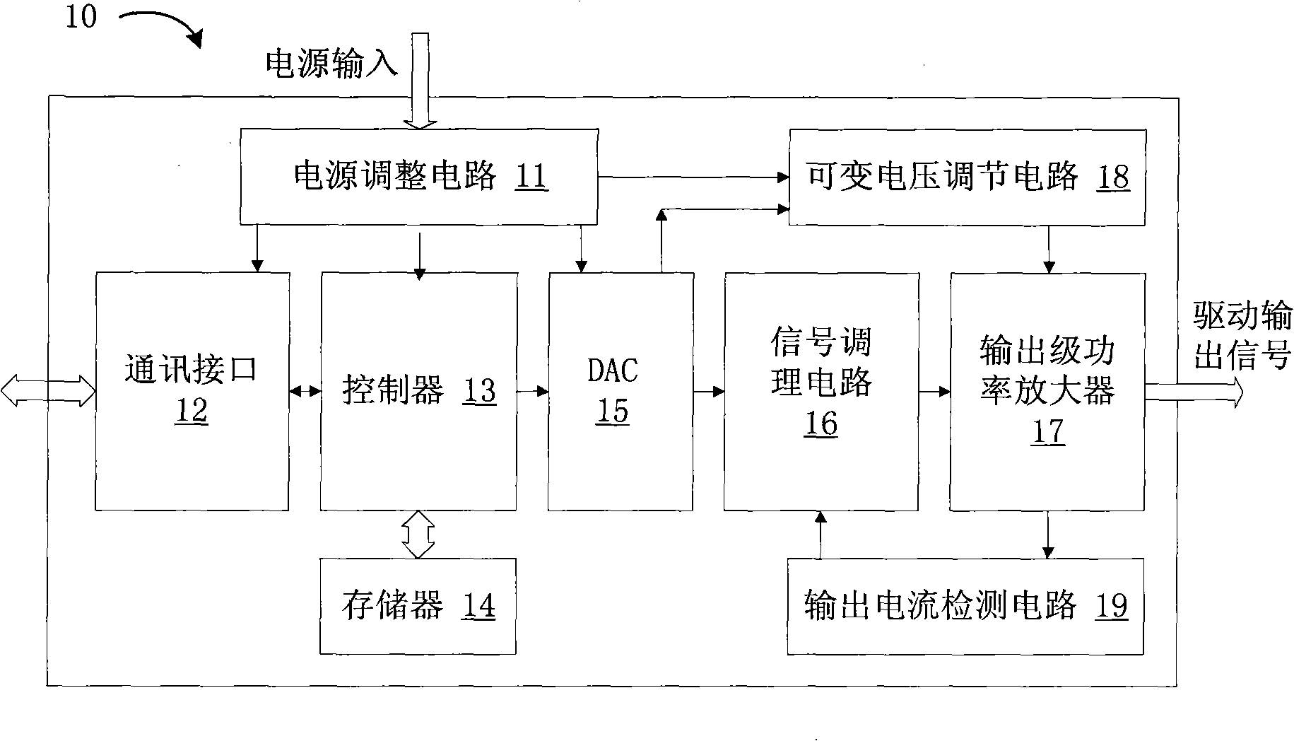
[0018] Please refer to figure 1 ,like figure 1 In one embodiment shown, the ultrasonic probe driving device 10 includes a power regulation circuit 11, a control unit, an output circuit 17 and a variable voltage regulation circuit 18, and each part will be described below.

[0019] Power supply adjustment circuit 11: provide energy input for each part of the entire driving device and the mechanical 3D ultrasonic probe. The power supply input can be DC voltage input, AC voltage input, or a combination of multiple AC and DC; power supply adjustment circuit 11 Adjust the power input to the voltage required by the other parts of the probe driver to operate properly, and power the various parts.

[0020] The control unit is configured to output a driving voltage command signal and a power supply voltage control signal according to user settings. In this embodiment, the control unit includes a controller, a digital-to-analog conversion circuit and a signal conditioning circuit.

...

Embodiment 2

[0037] This embodiment is an improved solution based on the above embodiments. The controller 13 in the ultrasonic probe driving device 10 also performs reverse hysteresis compensation on the probe, and corrects the position information of the ultrasonic image obtained in at least one direction of the forward scanning and reverse scanning of the probe.

[0038] Mechanical 3D ultrasonic probes usually integrate a home position sensor inside the probe, which is usually a switch type position sensor; when the probe swings to a certain angle, the sensor will output a pulse signal or perform level reversal, and the probe drive device according to this signal to reset.

[0039] In addition, we know that the speed of the probe is proportional to the frequency of the driving voltage, the speed of the probe can be controlled by controlling the frequency of the driving voltage, and the angle of the probe swing is proportional to the phase of the driving voltage; in order to control the ...

Embodiment 3

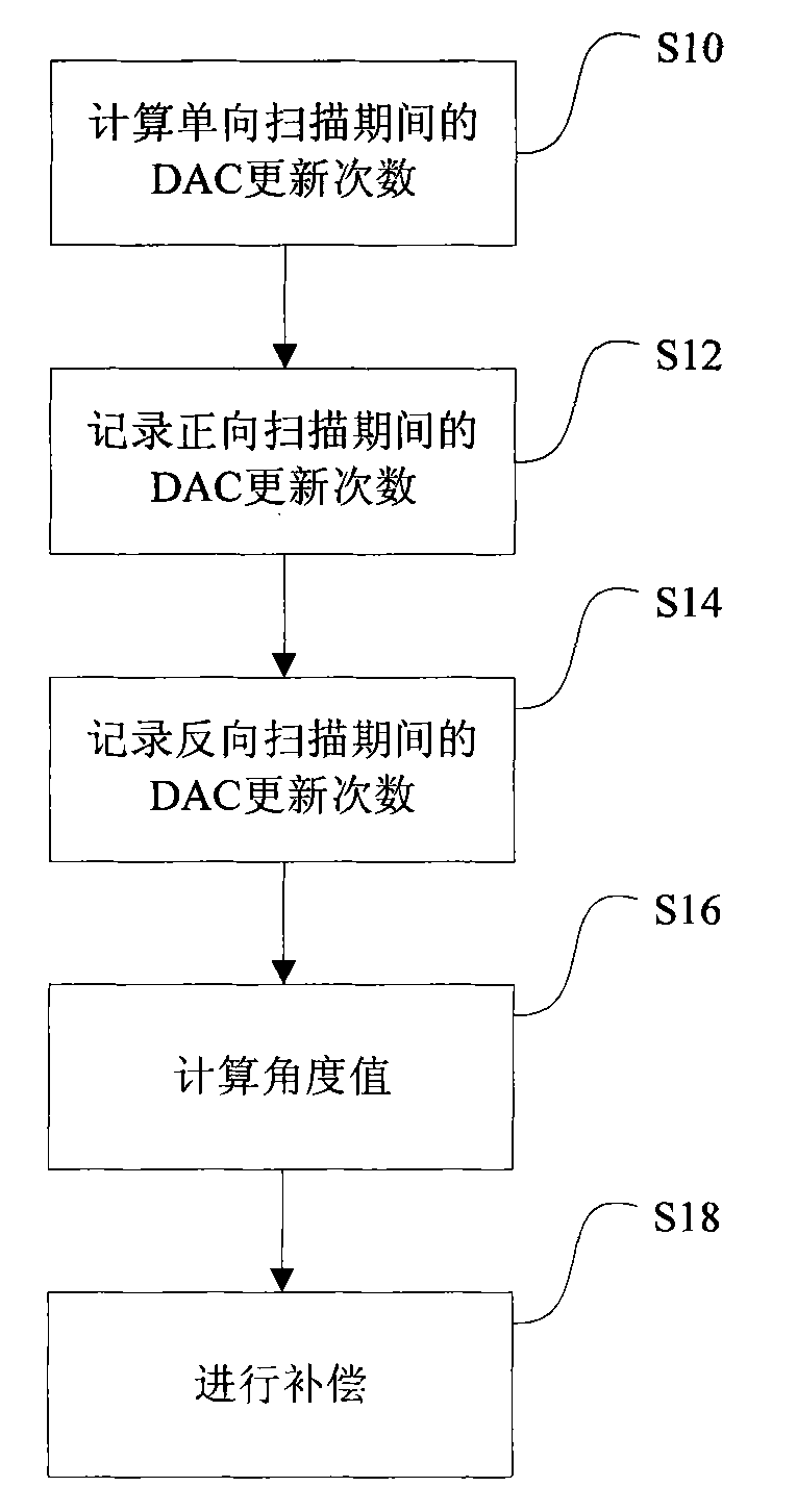
[0050] This embodiment is a further improvement on the basis of the above embodiments. The controller in the ultrasonic probe driving device is also used to control the speed of the probe. The controller controls the number of updates and the update time of the digital-to-analog conversion circuit in one scanning direction. Interval sequence to control the probe swing angle and swing speed.

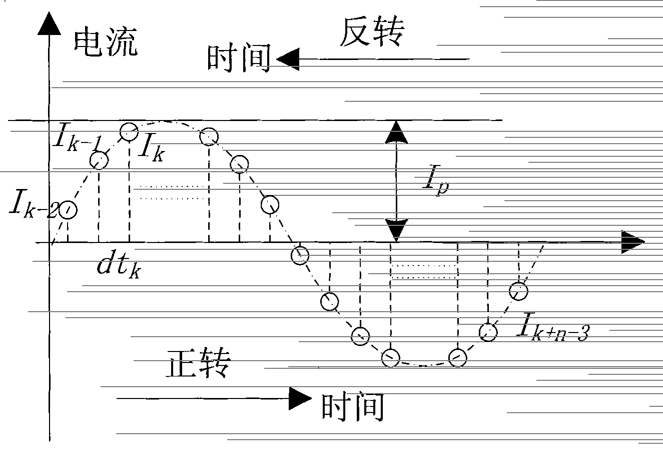
[0051] According to the second embodiment, a sine wave is divided into n parts at equal intervals to sample and output the current command signal. If the driving current waveform is cycled every cycle, and the angle of the probe swing is θ, then every interval, that is, every interval of the DAC One update means that the probe will swing by an angle of θ / n. In this way, controlling the time interval between two adjacent DAC data updates can control the frequency of the probe driving voltage, and then control the speed of the probe swing; controlling the number of DAC data updates can cont...


PUM


Abstract

The invention discloses a drive device for an ultrasonic probe and a drive method thereof. The drive device comprises a power supply regulating circuit, a control unit, an output circuit and a variable voltage regulating circuit, wherein the power supply regulating circuit is used for providing required voltages to each part of the drive device; the control unit is used for outputting driving voltage command signals and power supply voltage control signals according to settings of users; the output circuit comprises a power amplifier for outputting driving signals to the ultrasonic probe after amplifying the driving voltage command signal output by the control device; and the variable voltage regulating circuit is used for outputting variable power supply voltage to the power amplifier responding to the control unit. By adopting the invention, the power consumed on the power amplifier is reduced, the problem of serious heat generation of the drive device is solved, and the efficiency of the drive unit is improved.

Description

【Technical field】 [0001] The invention relates to an ultrasonic diagnostic instrument, in particular to an ultrasonic probe driving device and a driving method in the ultrasonic diagnostic instrument. 【Background technique】 [0002] The mechanical 3D ultrasonic probe is an important part of the three-dimensional or four-dimensional imaging system of the medical ultrasonic diagnostic instrument. Using the mechanical 3D ultrasonic probe to construct a three-dimensional or four-dimensional imaging system of the medical ultrasonic diagnostic instrument is usually based on such a method: at different angle positions Or spatial position acquisition to obtain multiple ultrasonic two-dimensional images to form an ultrasonic two-dimensional image sequence, and then use the two-dimensional image sequence and its corresponding position information to reconstruct a three-dimensional image or four-dimensional image according to a specific imaging algorithm. The difference between an imag...

Claims


Application Information

Patent Timeline
Patent Type & Authority Patents(China)
IPC IPC(8): A61B8/00
Inventor 谭泽伟
Owner SHENZHEN MINDRAY BIO MEDICAL ELECTRONICS CO LTD
Why Eureka
Try Eureka