Inverted pendulum balancing control system based on flywheel

A technology of balance control and inverted pendulum, applied in the field of intelligent robots, can solve the problems of poor mobility, affecting system control, low measurement accuracy, etc., and achieve the effects of increasing mobility, reducing difficulty, and avoiding accidental dumping.

Inactive Publication Date: 2010-10-06
BEIJING UNIV OF TECH
View PDF4 Cites 29 Cited by
  • Summary
  • Abstract
  • Description
  • Claims
  • Application Information

AI Technical Summary

Problems solved by technology

[0006] There are also many researchers abroad who are committed to the research of the inverted pendulum balance control system based on the flywheel. The representative one is the Model IP/NC Inverted Pendulum. This system uses 110 or 220 volts of AC power supply; the sensor uses an infrared sensor , it is an analog sensor, the measurement accu

Method used


Image

  • Inverted pendulum balancing control system based on flywheel
  • Inverted pendulum balancing control system based on flywheel
  • Inverted pendulum balancing control system based on flywheel

Examples


Embodiment 1

[0029] 1 mechanical structure

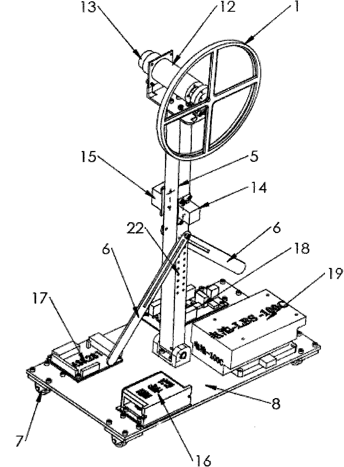
[0030] Present embodiment gross weight 7kg, height 700mm, length 400mm, width 320mm, corner wheel (7) diameter 38mm. The mechanical structure and electrical component layout of the inverted pendulum system are as follows ( figure 1 ):

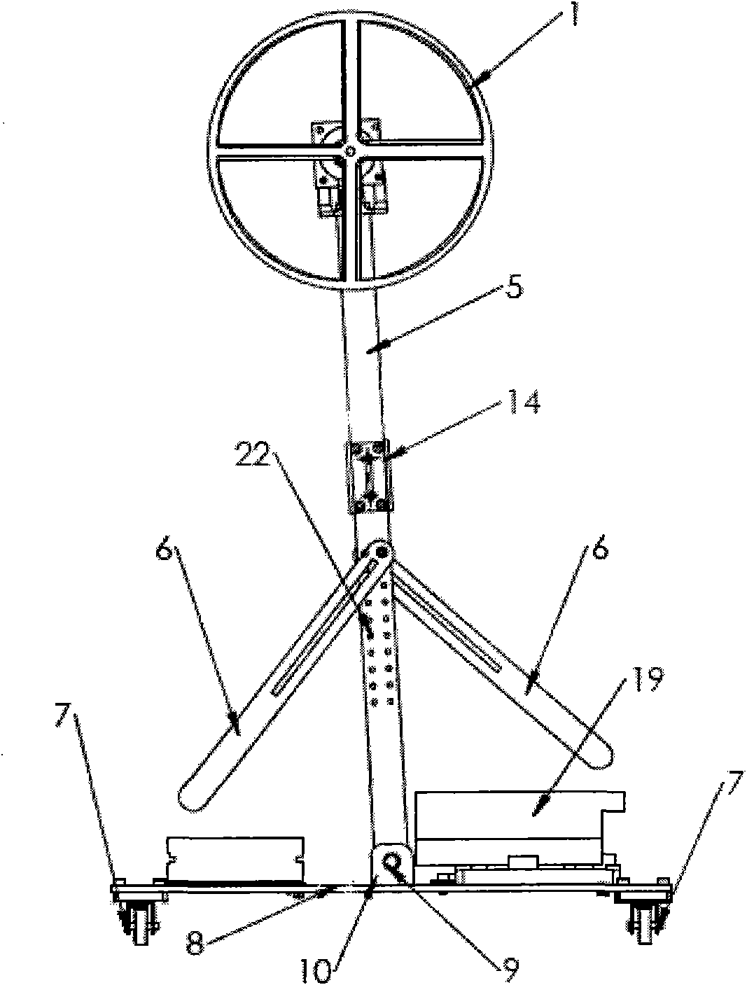
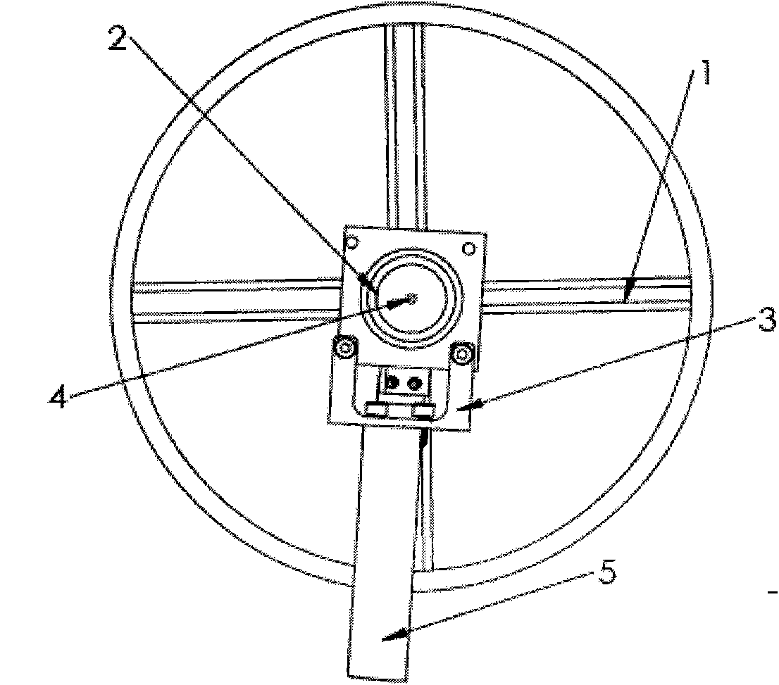
[0031] Such as figure 2, As shown in 3 and 4, the entire inverted pendulum is an aluminum alloy frame, mainly including a flywheel 1, a motor bushing 12, a swing rod 5, a swing rod side bracket 6, a base 8, and casters 7. A bearing 2 is used to connect the flywheel 1 and the motor bushing 12 . The motor sleeve 12 is connected with the swing rod 5 by using the motor bracket 3 . The flywheel 1 of the inverted pendulum system is a hollow cross support frame with a thicker aluminum alloy plate on the periphery, so that most of its mass is concentrated on the edge of the flywheel, increasing the moment of inertia of the flywheel. In order to reduce the friction of the flywheel when it rotates, this design Grind ...

Embodiment 2

[0047] The flywheel 1 of the inverted pendulum system is a hollow cross support frame with a thicker aluminum alloy plate on the periphery, so that most of its mass is concentrated on the edge of the flywheel, which increases the moment of inertia of the flywheel. In order to reduce the friction of the flywheel rotating, you can put The hollow cross support frame is ground into a certain degree of rounded corners to reduce resistance. A threaded shaft protrudes from the center of the cross support frame. By rotating this shaft into the rotation shaft of the motor (a shaft hole is reserved in the motor shaft in advance) ), instead of general vertical pressure, in order to protect the motor shaft, a bearing is installed on the outside of the motor shaft, at the end of the motor sleeve 12, and the end of the motor sleeve 12 has a motor end cover 11 to protect and fix the bearing , Avoid bending the motor shaft due to the weight of the flywheel, so that the flywheel will not be thr...

Embodiment 3

[0049] In the present invention, ten rows of small holes 21 are respectively reserved on the surface of both sides of the swing rod 5 on the base 8, two in each row, as Figure 7 shown. When the side brackets are removed, vertical protective frames 20 with adjustable distances are respectively placed on both sides of the swing rod 5, which can prevent that some components on the inverted pendulum may be damaged due to collisions when the swing rod is not well controlled for some reason , In addition, by adjusting the distance between the vertical protection frame and the swing rod, it can also be used to adjust the maximum deflection angle of the swing rod.


PUM


Abstract

The invention belongs to the category of intelligent robots, in particular to a static unbalanced robot capable of the self-control of balancing. The system controls a flywheel to rotate along the vertical direction with a DC servo motor so as to realize the balancing of the left and the right directions. In detection, in order to realize the posture self-detection of a pendulum bar in a swing process, an inertial navigation system based on an MEMS technology and an inclinometer are adopted to obtain the motion information of the pendulum bar. In safety, both sides of the pendulum bar are provided with pendulum bar side supports capable of conveniently adjusting the maximum angle of the pendulum bar, thereby not only protecting components in the system but also satisfying various control requirements in experiments. In order to reduce the control difficulty, some electronic devices, such as a power supply, a motion controller, a servo driver, a power adapter board and the like are arranged on a base, thereby reducing the pendulum bar control difficulty and improving the stability of the system. In mobility, casters with the brake function are arranged on the four corners of the base, thereby facilitating the debugging of the system in different places.

Description

technical field [0001] The invention belongs to the category of intelligent robots, in particular to a static unbalanced robot capable of autonomous motion balance control. Background technique [0002] The control of an inverted pendulum system is a typical example of the application of control theory. The mechanism is simple, the cost is low, and it is convenient to control by analog or digital methods. Although there are various structural forms, no matter what kind of structure it is, it is a non-minimum phase, multivariable, absolutely unstable nonlinear system. Due to the absolute instability of the inverted pendulum system, effective measures must be taken to control it. Its control method is widely used in military, aerospace, robotics and general industrial processes, such as balance control during robot walking, verticality control during rocket launch, and attitude control during satellite flight. . At the same time, due to the existence of friction, the syste...

Claims


Application Information

Patent Timeline
IPC IPC(8): B25J13/00
Inventor 阮晓钢王昱峰王启源于乃功宋科科
Owner BEIJING UNIV OF TECH
Why Eureka
Try Eureka