Displacement sliding rotary engine
A rotary engine and sliding vane technology, which is applied in the direction of rotary piston engine, rotary or swing piston engine, combustion engine, etc., can solve the problem of high engine processing cost and maintenance cost, low torque of triangular rotor engine, and inability to apply heavy vehicles, etc. problem, to achieve the effect of easy processing and maintenance, low processing cost and simple structure
- Summary
- Abstract
- Description
- Claims
- Application Information
AI Technical Summary
Problems solved by technology
Method used
Image

Examples
Embodiment Construction
[0028] 1. The first set of scheme structure of the present invention
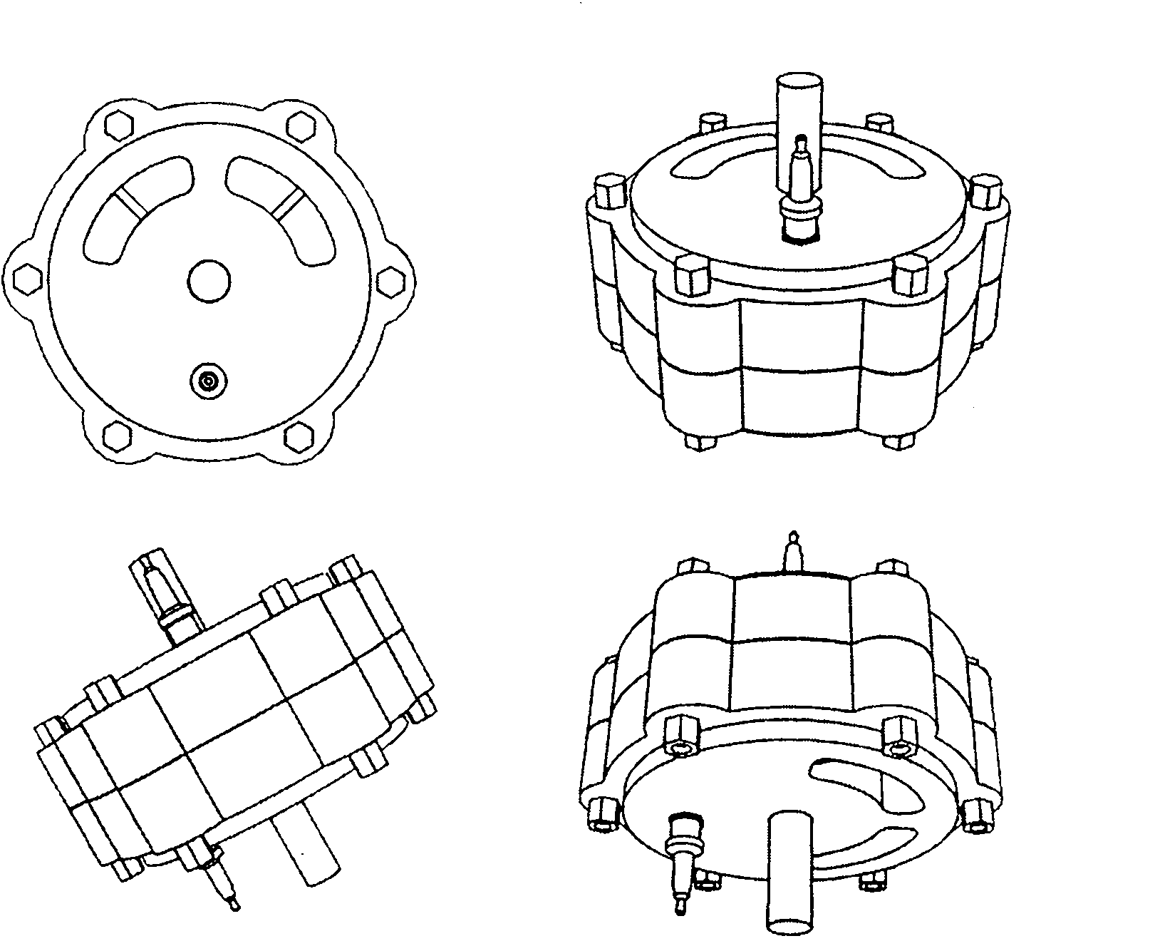
[0029] Such as figure 1 Shown is the schematic diagram of the appearance of the engine of the first set of schemes. From the figure, it can be understood that the shape of the engine of the present invention is a cylinder, and the output shaft (1) protrudes from the center point of the upper and lower top surfaces of the cylinder to connect the load. equipment. The stator of the motor is composed of upper and lower casings (3) opposed to each other, and is fixed by a plurality of casing bolts in a circle. On the upper and lower end faces of the cylinder, two upper and lower spark plugs with a difference of 90 degrees and two pairs of upper and lower gas ports with a difference of 90 degrees are installed with the output shaft as the axis.
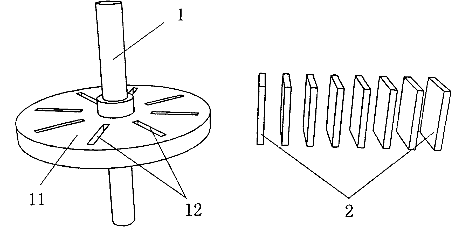
[0030] Such as figure 2 Shown is the schematic diagram of the rotor and the sliding vane of the first set of schemes of the present invention. In the figure, a disc ...
PUM
 Abstract
Description
Claims
Application Information
 - R&D
- Intellectual Property
- Life Sciences
- Materials
- Tech Scout
- Unparalleled Data Quality
- Higher Quality Content
- 60% Fewer Hallucinations
Browse by: Latest US Patents, China's latest patents, Technical Efficacy Thesaurus, Application Domain, Technology Topic, Popular Technical Reports.
© 2025 PatSnap. All rights reserved.Legal|Privacy policy|Modern Slavery Act Transparency Statement|Sitemap|About US| Contact US: help@patsnap.com