portable oxygen concentrator
An oxygen generator and portable technology, applied in the field of oxygen generators, can solve the problems of being unsuitable for portable use, the oxygen generator has large heat generation, and many parts and components, and achieves the effects of light weight, simple structure, and few parts and components.
- Summary
- Abstract
- Description
- Claims
- Application Information
AI Technical Summary
Problems solved by technology
Method used
Image
Examples
Embodiment 1
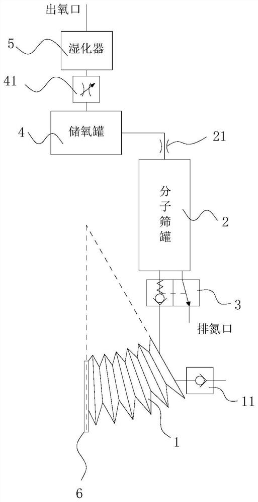
[0036] Such as figure 1 As shown, the portable oxygen concentrator includes a set of separation mechanisms and an oxygen storage tank 4; the separation mechanism includes an air bag 1 and a molecular sieve tank 2 (the molecular sieve tank is filled with molecular sieves for adsorption), and the molecular sieve tank 2 is connected to the oxygen storage tank 4;
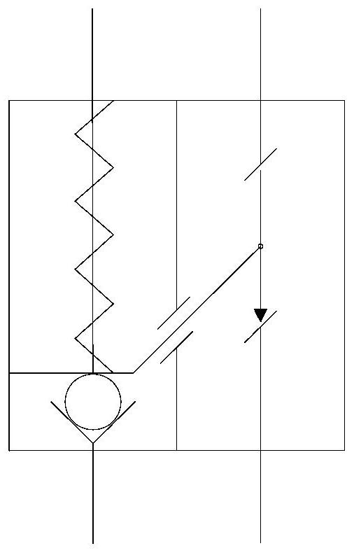
[0037] The airbag 1 is a structure whose internal space can be compressed and expanded. The airbag 1 has an air inlet for air entry and an exhaust outlet for air discharge. The airbag 1 is provided with a one-way valve 11. 2 connection, the valve group includes the linkage of the first single valve and the second single valve, the first single valve is a one-way pressure valve, the second single valve is a normally open valve, the exhaust port of airbag 1 passes through the first single valve and molecular sieve The bottom of the tank 2 is connected, and both ends of the molecular sieve tank 2 have at least one exhaust ...
Embodiment 2
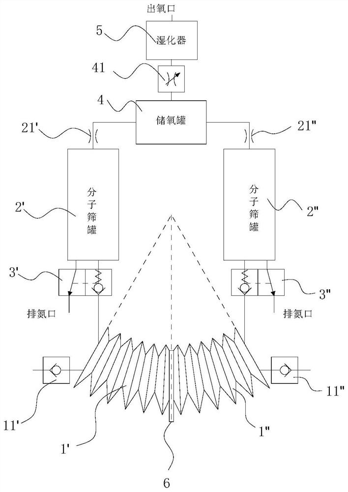
[0050] Such as image 3 As shown, in this embodiment, a group of separation mechanisms is added on the basis of the first embodiment above, and the two groups of separation mechanisms share an oxygen storage tank 4, an oxygen storage tank throttle valve 41, and a humidifier 5;
[0051] Such as image 3 The left airbag is the first airbag 1', the right airbag is the second airbag 1", the left one-way valve is the first one-way valve 11', the right one-way valve is the second one-way valve 11", the left The side molecular sieve tank is the first molecular sieve tank 2', the right molecular sieve tank is the second molecular sieve tank 2", the left throttle valve is the first throttle valve 21', and the right throttle valve is the second throttle valve 21" , the two-position two-way linkage one-way pressure valve on the left is the first two-position two-way linkage one-way pressure valve 3′, and the right two-position two-way linkage one-way pressure valve is the second two-pos...
Embodiment 3
[0063] Such as Figure 4 , Figure 5 As shown, the extruding plate 6 is equipped with a permanent magnet, and the left end of the first airbag 1' and the right end of the second airbag 1" all have an electromagnet structure, and the magnetic pole can be changed by changing the direction of the current, and the electromagnet structure and extrusion The permanent magnets of plate 6 attract and repel each other to realize the compression and expansion of the inner space of the airbag; Figure 4 As shown, the left side of the extrusion plate 6 is the N pole, the right side is the S pole, the left end of the second airbag 1 "is the N pole, and the right end of the first airbag 1' is the N pole, realizing the second airbag 1 " and the extrusion The plates 6 attract each other, and the first air bag 1' repels the extruded plates 6; as Figure 5 As shown, the left side of the extrusion plate 6 is the N pole, the right side is the S pole, the left end of the second airbag 1 "is the S...
PUM
 Abstract
Description
Claims
Application Information
 - R&D
- Intellectual Property
- Life Sciences
- Materials
- Tech Scout
- Unparalleled Data Quality
- Higher Quality Content
- 60% Fewer Hallucinations
Browse by: Latest US Patents, China's latest patents, Technical Efficacy Thesaurus, Application Domain, Technology Topic, Popular Technical Reports.
© 2025 PatSnap. All rights reserved.Legal|Privacy policy|Modern Slavery Act Transparency Statement|Sitemap|About US| Contact US: help@patsnap.com


