
Portable oxygenerator

An oxygen generator and portable technology, applied in the field of oxygen generators, can solve the problems of unsuitable for portable use, high heat generation and complex structure of oxygen generators, and achieve the effect of light weight, simple structure and small volume

Active Publication Date: 2020-10-09
ANHUI XIAOSHAN MEDICAL TECH CO LTD
View PDF14 Cites 1 Cited by
  • Summary
  • Abstract
  • Description
  • Claims
  • Application Information

AI Technical Summary

Problems solved by technology

[0013] The technical problem to be solved by the present invention is: how to solve the problem that the oxygen generator in the prior art has high calorific value, high noise, many parts, complex structure, high cost, and is not suitable for portable use

Method used


Image

  • Portable oxygenerator
  • Portable oxygenerator
  • Portable oxygenerator

Examples


Embodiment 1

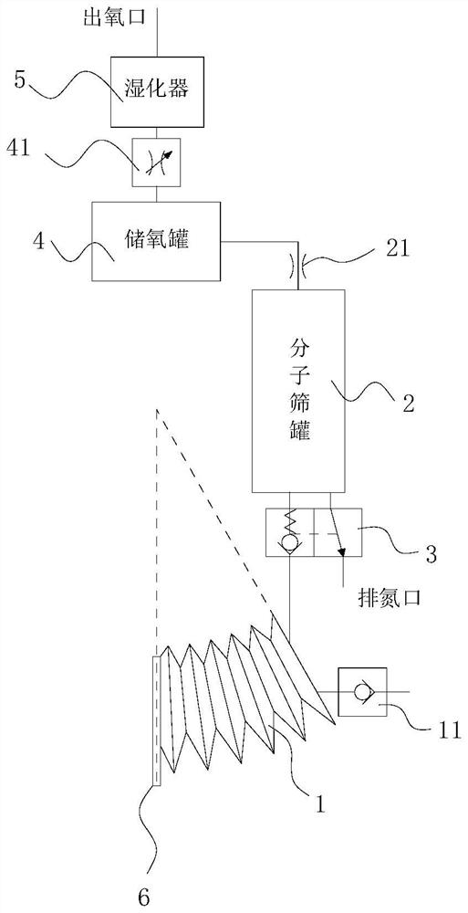
[0036] Such as figure 1 As shown, the portable oxygen concentrator includes a set of separation mechanisms and an oxygen storage tank 4; the separation mechanism includes an air bag 1 and a molecular sieve tank 2 (the molecular sieve tank is filled with molecular sieves for adsorption), and the molecular sieve tank 2 is connected to the oxygen storage tank 4;

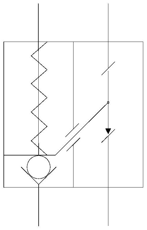
[0037] The airbag 1 is a structure whose internal space can be compressed and expanded. The airbag 1 has an air inlet for air entry and an exhaust outlet for air discharge. The airbag 1 is provided with a one-way valve 11. 2 connection, the valve group includes the linkage of the first single valve and the second single valve, the first single valve is a one-way pressure valve, the second single valve is a normally open valve, the exhaust port of airbag 1 passes through the first single valve and molecular sieve The bottom of the tank 2 is connected, and both ends of the molecular sieve tank 2 have at least one exhaust ...

Embodiment 2

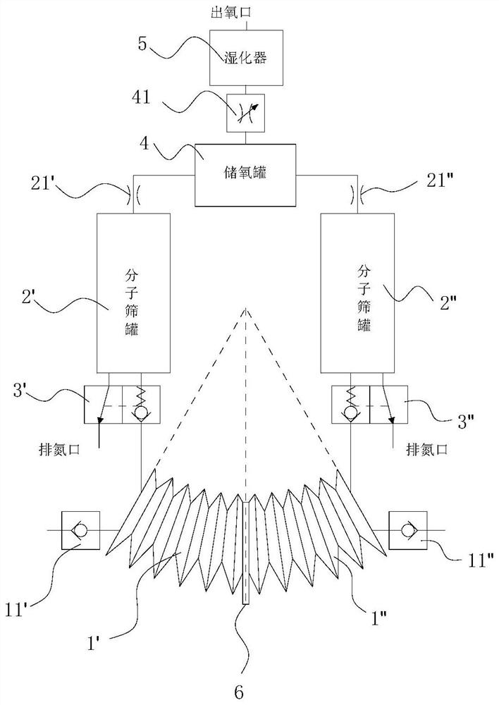
[0050] Such as image 3 As shown, in this embodiment, a group of separation mechanisms is added on the basis of the first embodiment above, and the two groups of separation mechanisms share an oxygen storage tank 4, an oxygen storage tank throttle valve 41, and a humidifier 5;

[0051] Such as image 3 The left airbag is the first airbag 1', the right airbag is the second airbag 1", the left one-way valve is the first one-way valve 11', the right one-way valve is the second one-way valve 11", the left The side molecular sieve tank is the first molecular sieve tank 2', the right molecular sieve tank is the second molecular sieve tank 2", the left throttle valve is the first throttle valve 21', and the right throttle valve is the second throttle valve 21" , the two-position two-way linkage one-way pressure valve on the left is the first two-position two-way linkage one-way pressure valve 3′, and the right two-position two-way linkage one-way pressure valve is the second two-pos...

Embodiment 3

[0063] Such as Figure 4 , Figure 5 As shown, the extruding plate 6 is equipped with a permanent magnet, and the left end of the first airbag 1' and the right end of the second airbag 1" all have an electromagnet structure, and the magnetic pole can be changed by changing the direction of the current, and the electromagnet structure and extrusion The permanent magnets of the plate 6 attract and repel each other to realize the compression and expansion of the inner space of the airbag; Figure 4 As shown, the left side of the extrusion plate 6 is the N pole, the right side is the S pole, the left end of the second airbag 1 "is the N pole, and the right end of the first airbag 1' is the N pole, realizing the second airbag 1 " and the extrusion The plates 6 attract each other, and the first air bag 1' repels the extruded plates 6; as Figure 5 As shown, the left side of the extrusion plate 6 is the N pole, the right side is the S pole, the left end of the second airbag 1 "is t...


PUM


Abstract

The invention discloses a portable oxygenerator which comprises at least one group of separation mechanism and an oxygen storage tank, and the separation mechanism is connected with the oxygen storagetank; the separation mechanism comprises an airbag and a molecular sieve tank; the molecular sieve tank is filled with a molecular sieve for adsorption; the airbag has an air inlet and an air outlet,and the valve group comprises a first single valve and a second single valve; the airbag is connected with the molecular sieve tank through a first single valve, two ends of the molecular sieve tankare respectively provided with at least one exhaust port, the exhaust port connected with the airbag is provided with a second single valve, the exhaust port at the other end is connected with the oxygen storage tank, the internal space of the airbag is compressed and expanded once, and molecular sieves in the molecular sieve tank are adsorbed and desorbed once. The portable oxygenerator has the beneficial effects of low noise, low heating and simple structure; the working process of the molecular sieve is synchronized through the working stroke of the airbag, and a corresponding electronic sensor, a single-chip microcomputer, a multi-way electromagnetic valve and a complex control circuit in a traditional device are omitted. Air bag compression and expansion can be achieved manually, andpower-off work can be achieved under special conditions.

Description

technical field [0001] The invention relates to a gas separation device, in particular to an oxygen generator. Background technique [0002] Pressure swing adsorption (abbreviated as PSA), as a gas separation technology, has attracted the attention of the industrial circles of various countries, and has developed rapidly. Its working principle is: the gas mixture is separated by using the difference in the adsorption performance of the adsorbent molecular sieve to different gas molecules. After the adsorption balance, according to the different characteristics of the adsorption amount of the molecular sieve at different pressures, the pressure is reduced to make the molecular sieve relieve the adsorption of the gas. Adsorption, this process is called regeneration. At present, pressure swing adsorption devices usually use two or more towers connected in parallel, so that pressure adsorption and decompression regeneration can be performed alternately, so as to obtain continuo...

Claims


Application Information

Patent Timeline
IPC IPC(8): C01B13/02
CPCC01B13/0259C01B2210/0028C01B2210/0046B01D53/047B01D2253/108B01D2256/12B01D2257/102B01D53/053B01D2259/4533B01D2259/402B01D53/0446B01D2253/116B01D2259/401B01D2259/4541C01B13/0274C01B2210/002
Inventor 雷激
Owner ANHUI XIAOSHAN MEDICAL TECH CO LTD
Learn More