A vapor-liquid separator

A technology of vapor-liquid separator and outlet connection, which is applied in refrigeration and liquefaction, lighting and heating equipment, refrigeration components, etc. It can solve problems such as roughness of the press-fitting part, difficulty in press-fitting of the copper outlet connection, and poor product consistency. The effect of welding fit distance stabilization

Active Publication Date: 2015-10-14
ZHEJIANG SANHUA INTELLIGENT CONTROLS CO LTD
View PDF5 Cites 1 Cited by
  • Summary
  • Abstract
  • Description
  • Claims
  • Application Information

AI Technical Summary

Problems solved by technology

[0005] When processing the gas-liquid separator according to the existing structure and process, because the flanging hole of the lower end cover 5 is designed with an inward flanging structure, and the iron straight pipe 4 is pressed from the inside to the outside, so the press-fitting is relatively difficult. The press-fitting part sometimes produces roughness, which will affect the welding quality during welding; and the lower end cover 5 adopts an inward flanging structure, and the copper outlet connecting pipe 6 can only be press-fitted on the reduced-diameter part 41 of the iron straight pipe 4 , that is, there are two interference fit press-fits at the welding part of the iron straight pipe. When the first press-fit is performed with the lower end cover 5, sometimes there will be roughening at the press-fit part, which will cause the gas-liquid separator to be welded in the furnace. When the solder penetrates into the napped part to produce welding bumps, it will make it difficult to press-fit the copper outlet connector 6 when it is pressed for the second time.
[0006] In addition, after the iron straight pipe 4 is press-fitted with the lower end cover 5, in order to press-fit with the copper outlet connection, the iron straight pipe 4 must protrude out of the lower end cover to a certain size, because there is a force point of impact after the straight pipe stretches out. In addition, the upper and lower end caps 5 are turned inward, and the iron straight pipe 4 is relatively easy to shrink inward after pressing, so that the iron straight pipe 4 may sometimes be impacted by an external force F during the circulation process of the assembly before the furnace welding process And shrinkage, resulting in relatively poor product consistency defects

Method used


Image

  • A vapor-liquid separator
  • A vapor-liquid separator
  • A vapor-liquid separator

Examples


Embodiment Construction

[0024] In order to enable those skilled in the art to better understand the technical solution of the present invention, further detailed description will be given below in conjunction with the accompanying drawings and specific embodiments.

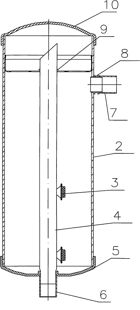
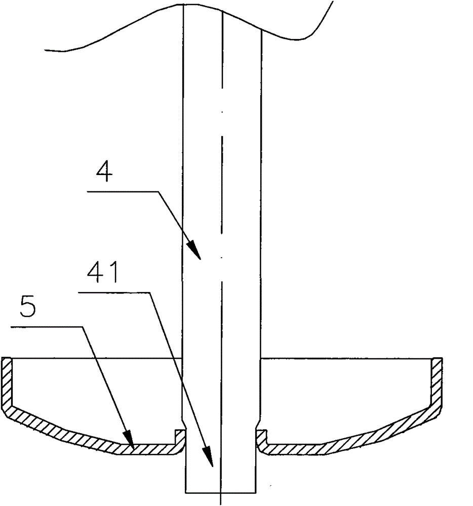
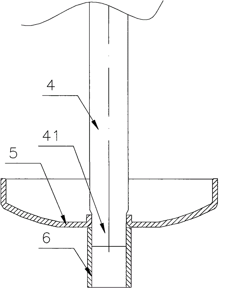
[0025] Figure 4 It is a structural schematic diagram of an embodiment of the vapor-liquid separator of the present invention, Figure 5 for Figure 4 The schematic diagram of the lower end cover of the gas-liquid separator and the iron pipe after pressing, Image 6 for Figure 4 Schematic diagram of the outlet connecting pipe of the gas-liquid separator after being press-fitted with the lower end cover and the iron pipe. As shown in the figure, the gas-liquid separator includes a cylinder body 2, an upper end cover 10 at the upper end of the cylinder body 2, and a lower end cover 15 at the lower end of the cylinder body 2. An iron bushing 8 is also fixed on the simplified body 2, and the lower end cover 15 is provided with a The out...


PUM

PropertyMeasurementUnit
heightaaaaaaaaaa

Abstract

The invention discloses a gas-liquid separator, which comprises a cylinder, an upper end cover, a lower end cover, an outlet adapter and an iron pipe. The iron pipe is positioned in the gas-liquid separator body; the outlet adapter is connected with the iron pipe through the lower end cover; the lower end cover is provided with an outward turnover edge part; the iron pipe is fixed with the inner wall of the outward turnover edge part of the lower end cover; and the outlet adopter is matched and fixed with the outer wall of the outward turnover edge part of the lower end cover by welding. Structural and technical improvements are made, so a welding fitting distance between the iron pipe and the lower end cover is stable, a galling phenomenon between welded contact surfaces is avoided and a welding fitting distance between the outlet adapter and the lower end cover is stable. Therefore, the quality, reliability and consistency among the lower end cover, the iron pipe and the outlet adapter are ensured.

Description

technical field [0001] The invention relates to a gas-liquid separation component in a refrigeration system, in particular to a gas-liquid separator processed by a furnace welding process. Background technique [0002] The vapor-liquid separator in the refrigeration system is a gas-liquid separation and oil return device, generally used in large and medium-sized refrigeration systems, and as figure 1 The shown is roughly installed vertically between the evaporator and the compressor of the refrigeration system, and its function is to separate the gas medium from the liquid medium to improve the operation quality and efficiency of the refrigeration system. Specifically: when the gas-liquid mixed medium produced in the evaporator flows into the gas-liquid separator through the copper inlet connection 7, the gas is separated from the gas and liquid in the cylinder of the gas-liquid separator and flows into the compressor through the copper outlet connection 6, and at the same t...

Claims


Application Information

Patent Timeline
Patent Type & Authority Patents(China)
IPC IPC(8): F25B43/00B23K31/02
Inventor 俞志辉
Owner ZHEJIANG SANHUA INTELLIGENT CONTROLS CO LTD
Why Eureka
Try Eureka