Vehicle running information acquisition device based on CAN (Controller Area Network) bus

A CAN bus and information acquisition technology, applied in the field of data acquisition devices, can solve problems such as poor compatibility, large number of pulse signals, expensive acquisition tools, etc., achieve convenient acquisition, data security, and reduce economic and time losses.

Inactive Publication Date: 2010-10-06
HIGER
View PDF5 Cites 21 Cited by
  • Summary
  • Abstract
  • Description
  • Claims
  • Application Information

AI Technical Summary

Problems solved by technology

[0004] 1. Professional service personnel are required to go to the real vehicle, which is time-consuming and laborious. The collection of driving data requires specialized personnel to follow the vehicle for testing, and also needs to carry laptops, inverters and other related equipment;
[0005] 2. Less data is collected and the scope of diagnosis is limited. Special diagnostic equipment is required for engines, gearboxes, ABS (Anti-lock Braking System, anti-lock braking system), and the diagnostic equipment for one component cannot diagnose the faults of other equipment at the same time , the compatibility is poor, often a set of diagnostic equipment can only diagnose the engine or parts of the same company;
[0006] 3. In order to collect a variety of data, the same vehicle needs several different diagnostic equipment, but the dedicated collection tools are expensive, and it is impossible to install them on every vehicle, and it is impossible to collect data every day;
[0007] 4. For the switching signal and pulse signal of the equipment, there are many types and various types, which are not easy to collect, and the statistics are more complicated

Method used


Image

  • Vehicle running information acquisition device based on CAN (Controller Area Network) bus
  • Vehicle running information acquisition device based on CAN (Controller Area Network) bus

Examples


Embodiment

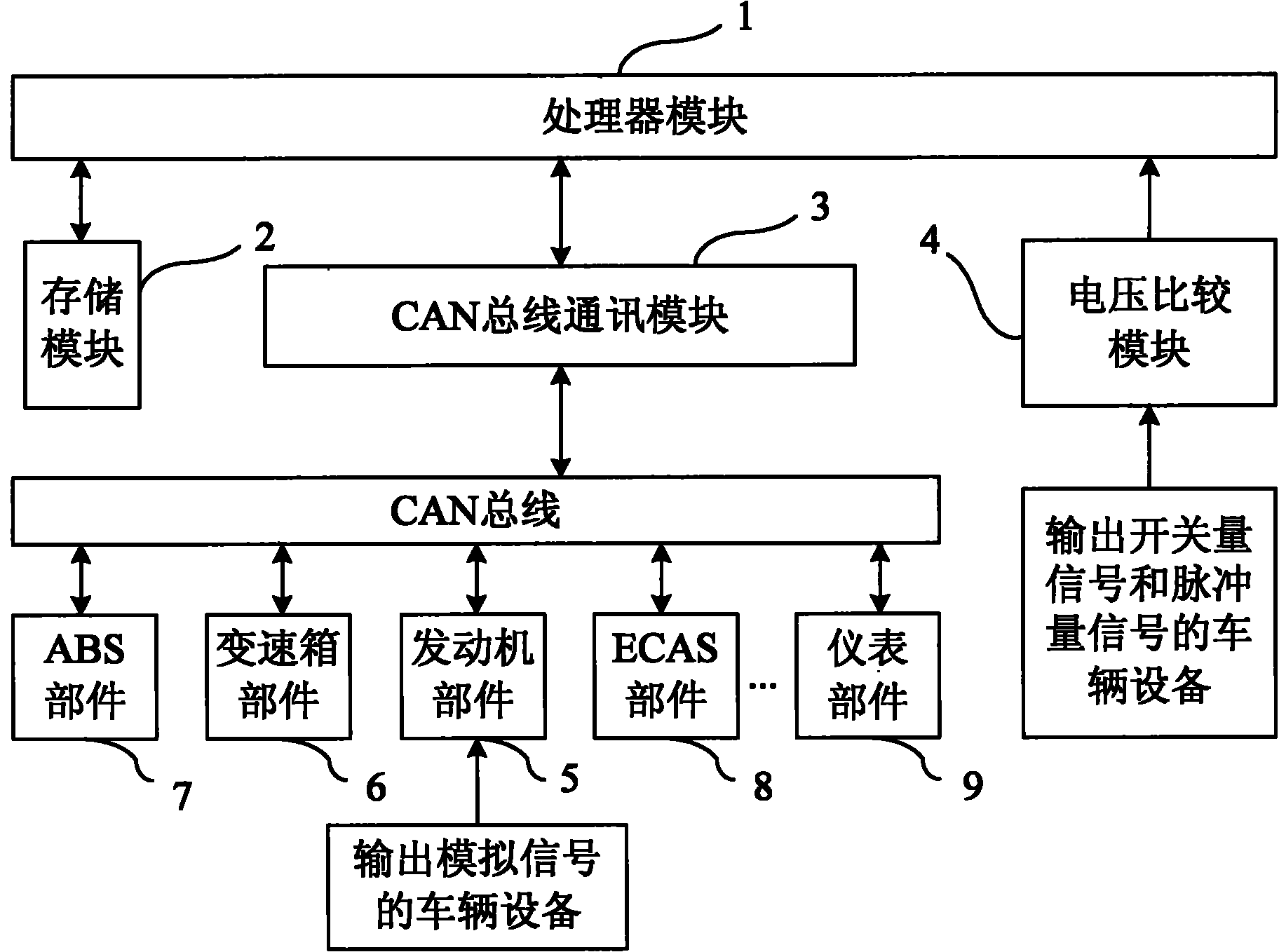
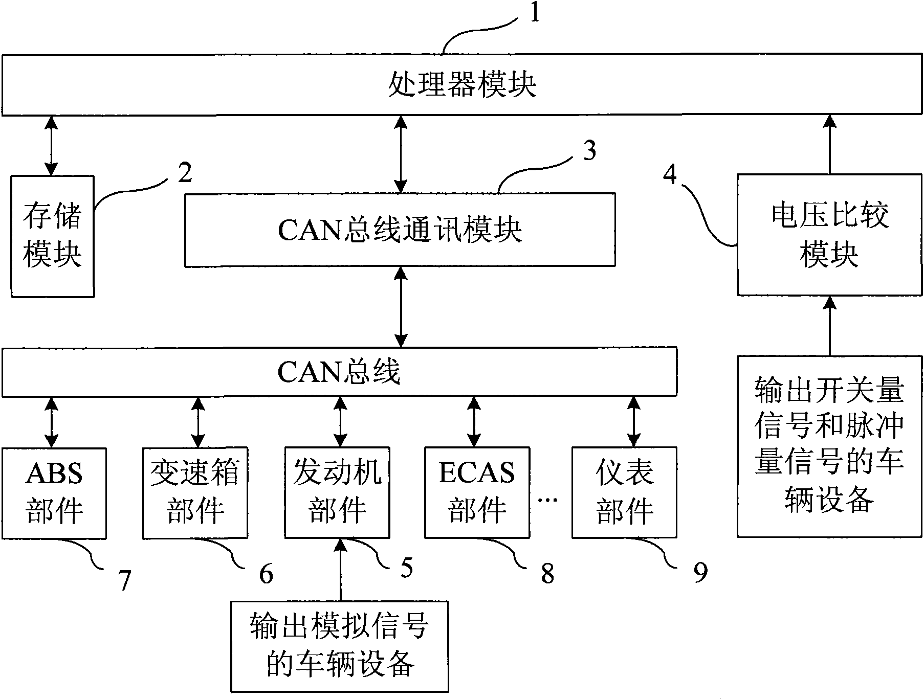
[0029] Example: such as figure 1 As shown, the vehicle operation information collection device based on CAN bus in this embodiment includes a processor module 1 , a storage module 2 connected to the processor module, a CAN bus communication module 3 and a voltage comparison module 4 . The input signal of the voltage comparison module 4 is the switching signal and the pulse signal output by the vehicle equipment, and the output terminal of the voltage comparison module 4 is connected to the processor module 1; the analog signal output by the vehicle equipment is processed by the engine ECU and then transmitted to CAN On the bus, it is received by the CAN bus communication module 3, and the CAN bus communication module 3 also receives other equipment signals hanging on the CAN bus. Convert CAN bus data into SPI bus data, and then transmit to processor module 1. Specifically, the CAN bus communication module includes a CAN bus transceiver that receives data from the CAN bus and ...


PUM


Abstract

The invention discloses a vehicle running information acquisition device based on a CAN (Controller Area Network) bus, comprising a processor module, a storage module, a CAN bus communication module and a voltage comparison module, wherein the storage module, the CAN bus communication module and the voltage comparison module are respectively connected with the processor module; input signals of the voltage comparison module are switching value signals and pulse value signals which are output by vehicle equipment, and the output end of the voltage comparison module is connected with the processor module; analog value signals output by the vehicle equipment are processed by an engine ECU (Electronic Control Unit), then transmitted to the CAN bus and received by the CAN bus communication module; the CAN bus communication module is also used for receiving other equipment signals hung on the CAN bus; and the output end of the CAN bus communication module is connected with the processor module through an SPI (Serial Peripheral Interface) bus. The device can be used for acquiring various equipment information on the vehicle, the acquisition is more convenient and comprehensive, and references are provided for the aspects of oil consumption management, driver operation specifications, the judgment of whether the power configuration of the vehicle design is reasonable or not as well as the improvement and the judgment on whether the vehicle needs to be maintained or not according to acquired data.

Description

technical field [0001] The invention relates to a data acquisition device for vehicle equipment. Background technique [0002] With the rapid development of on-board electronic products, passenger cars are one of the main means of transportation. In order to improve their driving comfort, more and more electronic auxiliary control devices are added to passenger cars. These devices are high-tech electronic products. At present, the performance and maintenance ability of domestic drivers on passenger car electronic products are uneven, and it is difficult to analyze or describe the reasons when electronic products fail. Therefore, it is difficult for vehicle operating companies and bus manufacturers to obtain first-hand information on vehicle operation status and failure causes in a timely manner, and it is difficult to effectively control subsequent operation system management, improvement of driving habits, and troubleshooting and maintenance. [0003] The data collection m...

Claims


Application Information

Patent Timeline
Patent Type & Authority Applications(China)
IPC IPC(8): G05B19/418H04L29/08
CPCY02P90/02
Inventor 邱峰谢江宏魏建彬高正平张世平范宣禄徐毛五方元华
Owner HIGER
Why Eureka
Try Eureka