
Networking control method and automatic flushing system of flushers used in public toilet

An automatic flushing and network control technology, applied in the field of public health, can solve the problems of insufficient flushing, poor scalability, waste of water resources, etc., and achieve the effects of avoiding water pressure drop, ensuring public health, and saving water resources

Inactive Publication Date: 2013-06-19
耿会超
View PDF5 Cites 0 Cited by
  • Summary
  • Abstract
  • Description
  • Claims
  • Application Information

AI Technical Summary

Problems solved by technology

[0002] At present, the known automatic squatting flushers for toilets all adopt a single-body design and work independently, and are composed of an active infrared induction control device and a solenoid valve. When it is used in a place with a large number of users, many squatting positions are flushed at the same time, resulting in a drop in water pressure, insufficient flushing, adverse effects on the public health environment and a waste of water resources; the patent document with the application number 200510049867.7 discloses a A one-to-many group control scheme using a single-chip microcomputer to control multiple flushers including sensors and solenoid valves, and pointed out that the scheme saves single-chip microcomputers, but the scheme has poor scalability. If the number of flushers to be controlled increases, it must be redesigned The circuit even has to replace the single-chip microcomputer due to insufficient resources of the single-chip microcomputer; and the stability of the scheme is poor, if the control circuit or the single-chip microcomputer fails, all flushers will not work; finally, the sensor adopts an active infrared sensing method, because its characteristics are easily affected by light, False alarms occur when strong light (e.g. lights, sunlight) shines

Method used


Image

  • Networking control method and automatic flushing system of flushers used in public toilet
  • Networking control method and automatic flushing system of flushers used in public toilet
  • Networking control method and automatic flushing system of flushers used in public toilet

Examples


Embodiment 1

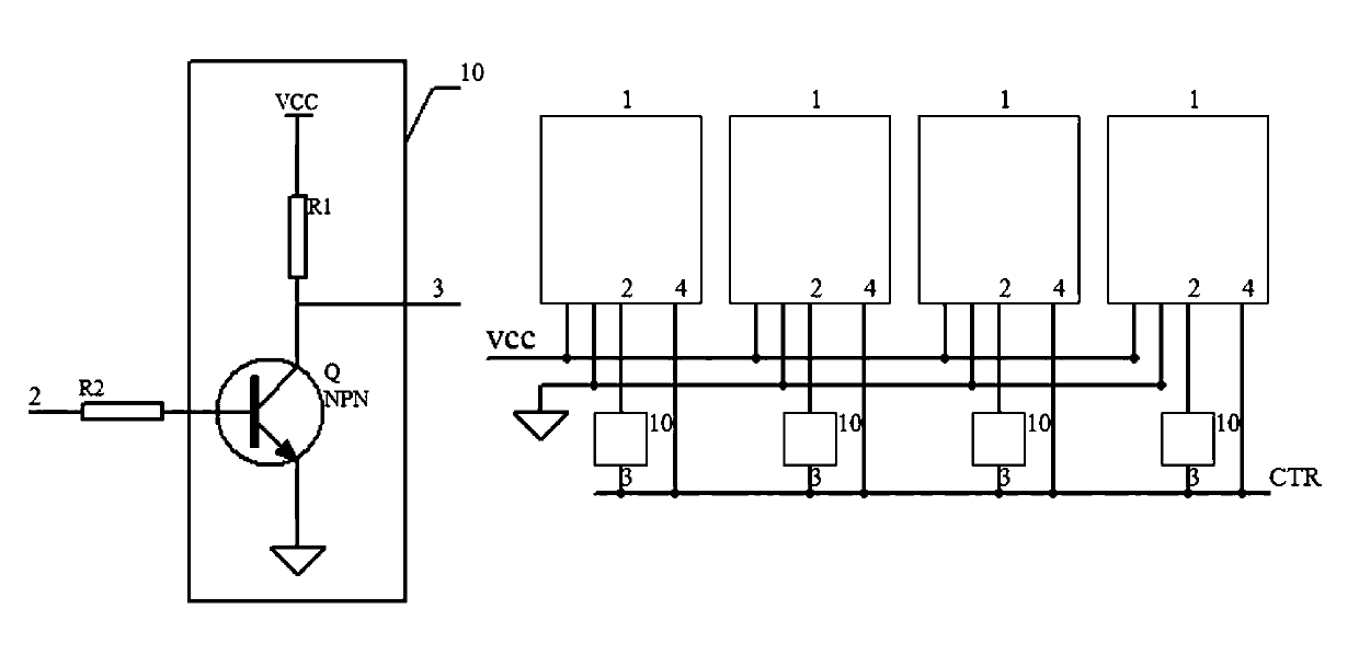
[0024] Such as figure 1 Shown is the automatic flushing system adopting the network control method of the present invention, including a group of flushers with sensors, single-chip microcomputers 1 and solenoid valves respectively set corresponding to each squatting position, and each single-chip microcomputer 1 communicates with a bus through a control circuit 10 Connected, the bus includes power lines (VCC and signal ground) and a control line CTR. The control circuit 10 is composed of a triode Q and current limiting resistors (R1, R2). NPN triode Q base is connected to one I / O port 2 of MCU 1 through current limiting resistor R2, collector 3 is connected to control line CTR, and connected to power supply VCC through another current limiting resistor R1, and the emitter is grounded; the other of MCU 1 The I / O port 4 is directly connected to the control line CTR.

[0025] In order to reduce the misoperation of the sensing sanitary ware, we choose the ultrasonic sensor as th...

Embodiment 2

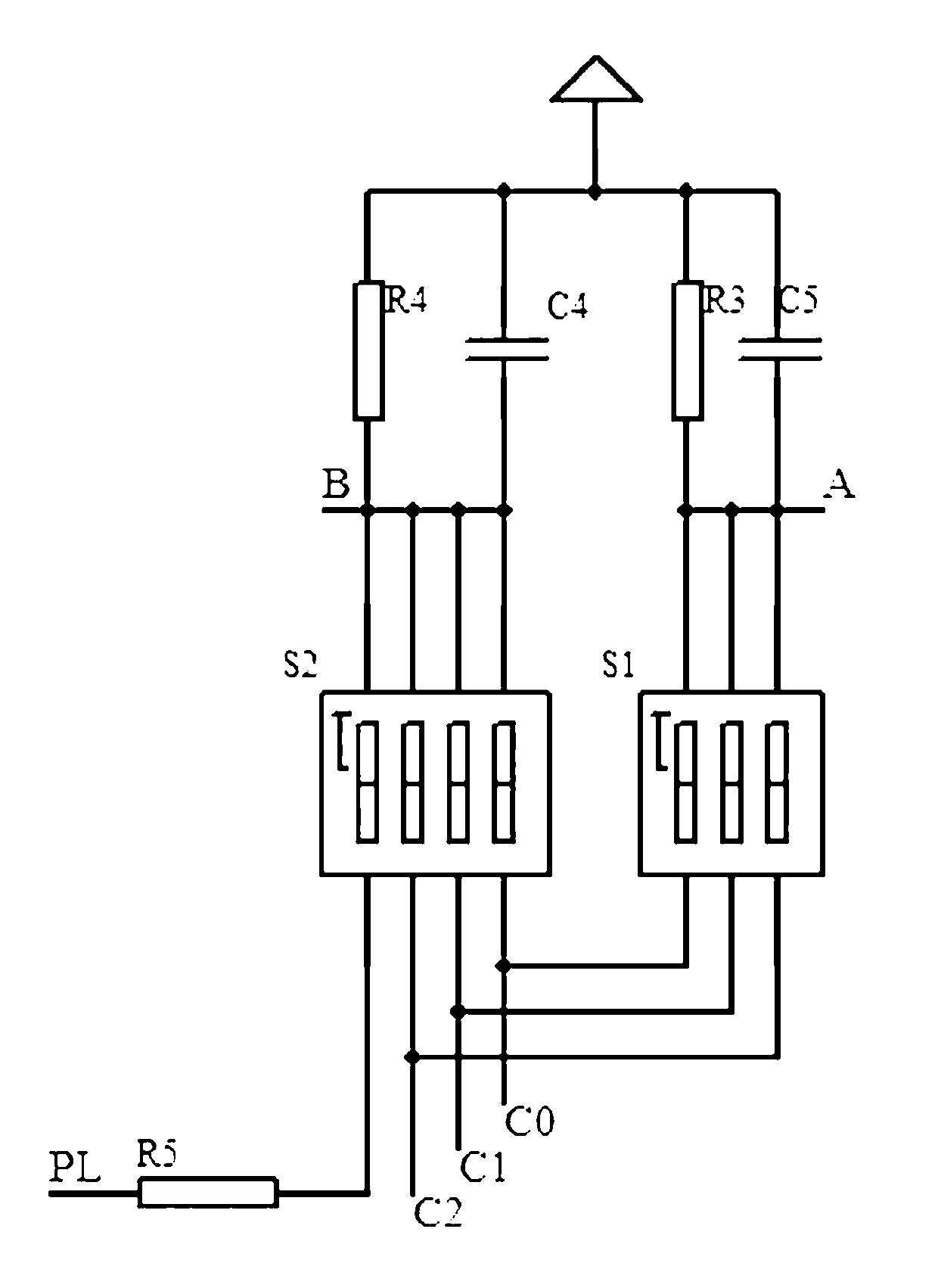
[0030] In Embodiment 2, still a flusher corresponds to each flusher with a sensor, solenoid valve and single-chip microcomputer 1, and is connected to the bus through the port circuit 20, but the bus is different from that in Embodiment 1, including power lines (VCC, GND) and communication lines (SO, SI), the port circuit 20 is to set a resistor R21 between the microcontroller 1 and the output line SO, and set a reverse diode D21 between the input line SI; and, it also has an encoding circuit, such as figure 2 shown. With this circuit structure, any single-chip microcomputer can be used as the host to manage other single-chip microcomputers, thereby controlling the entire flushing system. Therefore, it is necessary to encode the addresses of each single-chip microcomputer to facilitate their communication with the host computer. Process such as Figure 8 As shown, the system initialization stage: scan the state of the DIP switch S1, then communicate with the host to inform t...

Embodiment 3

[0032] The system of embodiment 3 such as Figure 5 As shown, the difference with Embodiment 2 is only that a single-chip microcomputer 30 specially used as the control host is added, and the information of each flushing device is passed to the main frame by the bus, and the control signal is sent to the single-chip microcomputers of each flushing device by the main frame. Control their flushing operation.


PUM


Abstract

The invention relates to a networking control method and an automatic flushing system of flushers used in a public toilet. Each squatting position in the public toilet is provided with one flusher provided with a sensor, a single-chip and an electromagnetic valve. The control method comprises the following steps of: a) connecting the single-chip of each flusher together by using a bus; b) detecting the squatting position by the sensor, from the time when a person is detected at the squatting position to the time when the person leaves the squatting position, recording the residence time of the person at the squatting position; and c) when detecting that the person leaves the squatting position, checking whether other flushers are flushing at that time, if so, waiting, otherwise, flushing.The automatic flushing system adopting the method controls each flusher in a unified mode to avoid water pressure reduction caused by flushing at the same time so as to guarantee public health and save water resources; and simultaneously, with the adoption of a one-to-one modularized design, the scheme has extremely strong adaptability and expandability to various systems, faults of a single controller cannot influence the normal work of other flushers, so the stability is very strong.

Description

technical field [0001] The invention relates to the field of public health, in particular to automatic flushing equipment for public toilets. Background technique [0002] At present, the known automatic squatting flushers for toilets all adopt a single-body design and work independently, and are composed of an active infrared induction control device and a solenoid valve. When it is used in a place with a large number of users, many squatting positions are flushed at the same time, resulting in a drop in water pressure, insufficient flushing, adverse effects on the public health environment and a waste of water resources; the patent document with the application number 200510049867.7 discloses a A one-to-many group control scheme that uses a single-chip microcomputer to control multiple flushers including sensors and solenoid valves. It is pointed out that the scheme saves single-chip microcomputers, but the scalability of the scheme is poor. If the number of flushers to be...

Claims


Application Information

Patent Timeline
Patent Type & Authority Patents(China)
IPC IPC(8): G05B19/418E03D5/10
Inventor 耿会超
Owner 耿会超
Learn More