Osmotic pressure measuring device for high water pressure test system

A test system, high-pressure water pressure technology, applied in the direction of measuring devices, measuring fluid pressure, permeability/surface area analysis, etc., can solve the problem of failure to achieve effective measurement of osmotic pressure, failure of osmotic pressure measurement of osmotic pressure holes, construction Quality is difficult to guarantee and other issues, to avoid the failure of osmotic pressure measurement, simple and reliable structure, and convenient installation

Active Publication Date: 2010-10-13
POWERCHINA ZHONGNAN ENG
View PDF4 Cites 13 Cited by
  • Summary
  • Abstract
  • Description
  • Claims
  • Application Information

AI Technical Summary

Problems solved by technology

The disadvantage of this process is that during the grouting process, it is easy to cause the piezometer to be cemented by the cement slurry poured in later, resulting in the failure of the piezometer, and the effective measurement effect of seepage pressure cannot be achieved, an...

Method used


Image

  • Osmotic pressure measuring device for high water pressure test system
  • Osmotic pressure measuring device for high water pressure test system

Examples


Embodiment Construction

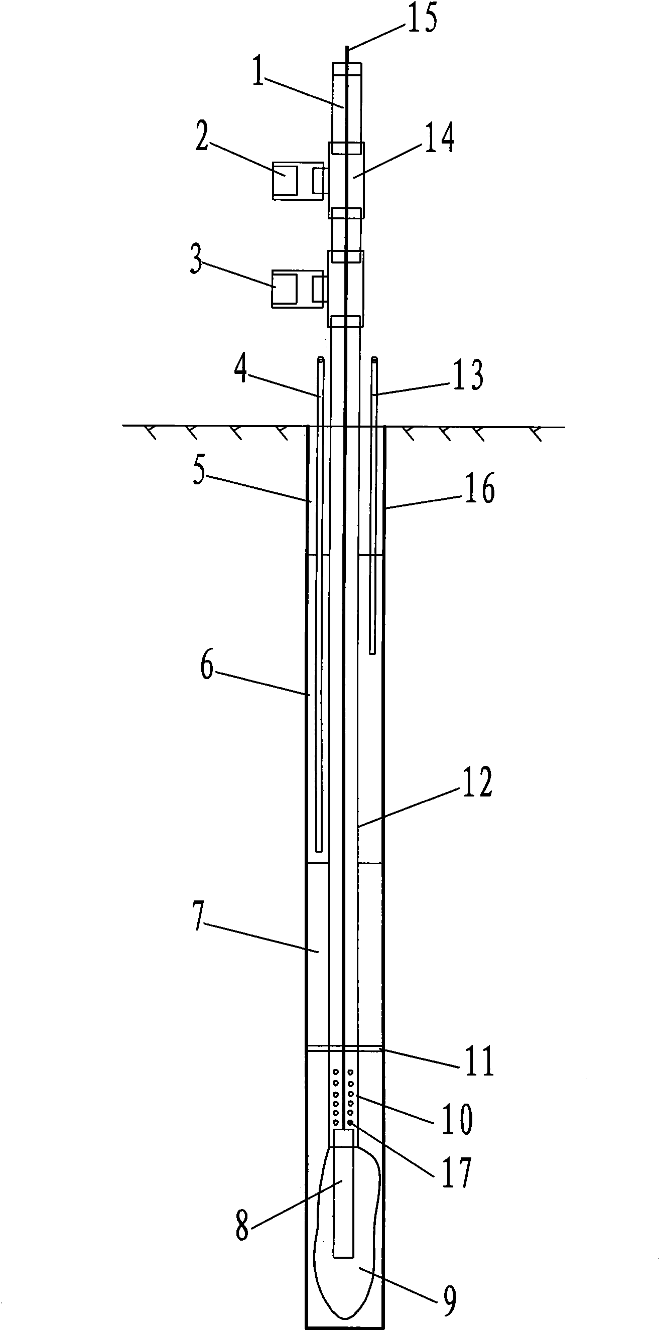
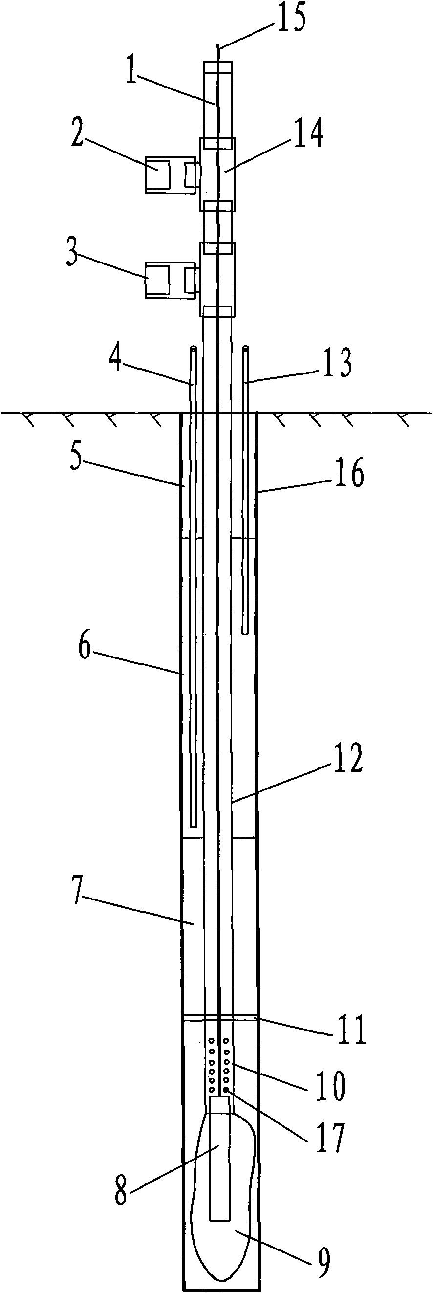
[0016] Such as figure 1 As shown, the present invention includes a seepage hole 16 opened in the rock body, and one end of a seamless steel pipe 12 stretches into the bottom of the seepage hole 16 . A piezometer 8 is fixed on the bottom of the seamless steel pipe 12, and its cable 15 passes through the seamless steel pipe 12 and stretches out of the seepage hole 16, and the outer surface of the piezometer 8 is covered with a protective sand bag 9. Above the seamless steel pipe 12 one end of the fixed piezometer 8, a flower pipe section 10 with a length of 20 cm is set, that is, the flower pipe section 10 is provided with a water hole 17 that runs through inside and outside, so that the water body inside the seamless steel pipe and outside the piezometer 8 connected. A rubber clapboard 11 is set on the outer side of the flower tube section 10 of the seamless steel pipe at 15 cm above, and the water-stop kelp 7 is bound up from the rubber clapboard 11 within the range of 100 cm...


PUM


Abstract

The invention relates to an osmotic pressure measuring device for a high water pressure test system. The device comprises that: an osmotic pressure hole is formed in rock mass; one end of a seamless steel tube stretches into the bottom of the osmotic pressure hole; an osmometer is fixed at the bottom of the seamless steel tube; an osmometer cable passes through the seamless steel tube and stretches out of the osmotic pressure hole; an osmometer cable leading-out end of the seamless steel tube is blocked by an epoxy resin plug; one end of the seamless steel tube, which fixes the osmometer, is provided with a floral tube section; the outer side of the seamless steel tube above the floral tube section is provided with a rubber clapboard; a water stop kelp is bound on the rubber clapboard; an injection pipe is arranged in the osmotic pressure hole and stretches into the water stop kelp; a position above the water stop kelp of the osmotic pressure hole is blocked by a pure expanding cement block section; a position near the orifice of the osmotic pressure hole is blocked by a cement mortar plug; and an exhaust pipe is also arranged in the osmotic pressure hole and stretches into the pure expanding cement block section. The device has the advantages of simple structure, convenient operation and capability of effectively ensuring the reliability of a measuring element.

Description

technical field [0001] The invention relates to an osmotic pressure measuring device used in in-situ high pressure water permeability tests of rock mass in the fields of water conservancy and hydropower engineering, water supply engineering, petroleum engineering, etc., especially for the osmotic pressure used when the rock mass osmotic pressure is high measuring device. Background technique [0002] Under the existing technical conditions, the pressure holes in the high-pressure water test are generally simply grouted and plugged with modified cement mortar or modified cement slurry. The disadvantage of this process is that during the grouting process, it is easy to cause the piezometer to be cemented by the cement slurry poured in later, resulting in the failure of the piezometer, and the effective measurement effect of seepage pressure cannot be achieved, and its construction quality is difficult to guarantee. . At the same time, since only one piezometer is installed a...

Claims


Application Information

Patent Timeline
IPC IPC(8): G01L11/00G01N15/08
Inventor 李尚高蒋中明冯树荣胡大可傅胜许利辉
Owner POWERCHINA ZHONGNAN ENG
Why Eureka
Try Eureka