

Car fault diagnosis remote alarming system and method
A remote alarm and vehicle failure technology, applied in alarms, transmission systems, instruments, etc., can solve the problems of increased vehicle failures, difficulty in judging the cause of failures, and impossibility of collecting data every day, so as to prevent related equipment from being damaged and reduce The probability of breaking down halfway and the effect of reducing vehicle maintenance costs
- Summary
- Abstract
- Description
- Claims
- Application Information
AI Technical Summary
Problems solved by technology
Method used
Image

Examples
Embodiment 1
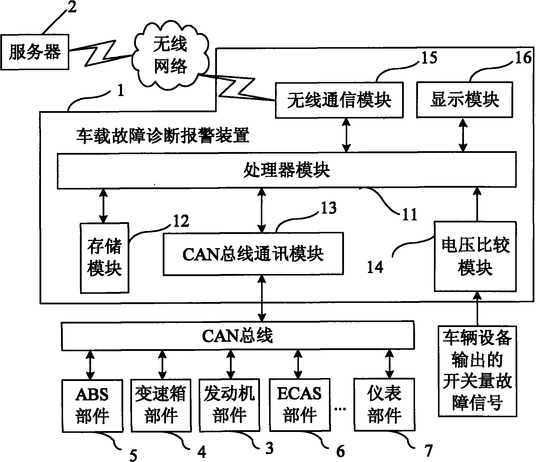
[0040] Embodiment 1: A vehicle-mounted fault diagnosis and alarm device 1 of the present embodiment is as figure 2 As shown in , it includes a processor module 11 , a CAN bus communication module 13 , a voltage comparison module 14 , a wireless communication module 15 and a display module 16 . Wherein, the CAN bus communication module 13 , the voltage comparison module 14 , the wireless communication module 15 , and the display module 16 are respectively connected to the processor module 11 .
[0041] The voltage comparison module 14 is used for comparing and judging the fault signal output by the vehicle equipment in the form of a switch, and its output terminal is connected to the input terminal of the processor module 11 . At present, the fault signals in the form of switching quantities output by the vehicle equipment include brake shoe wear signals and air filter clogging fault signals.
[0042] Other equipment failure signals are sent by the vehicle equipment to the CAN ...
Embodiment 2
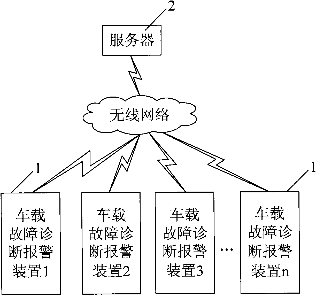
[0059] Embodiment 2: For the vehicle fault diagnosis remote alarm system with many vehicle fault diagnosis alarm devices, it is far from enough to carry out direct communication by the vehicle fault diagnosis alarm device and the remote server, so between the vehicle fault diagnosis alarm device and the server There are several collection and control gateways 8, such as Figure 4 shown. The acquisition and control gateway 8 refers to a gateway that collects data from the vehicle-mounted fault diagnosis and alarm device and transmits the data to the server, or transmits the control instructions from the server to the vehicle-mounted fault diagnosis and alarm device. Since the number of on-board fault diagnosis and alarm devices that can be connected to each acquisition and control gateway is limited, it must be managed in a distributed manner. The on-board fault diagnosis and alarm device first communicates with the acquisition and control gateway in real time. At present, eac...
PUM
 Abstract
Description
Claims
Application Information