Turn-on angle control method for switched reluctance motor
A technology of switched reluctance and control method, applied in current controllers, electronic commutators, etc., can solve problems such as large amount of table calculation, complex process, lack of versatility, etc. Universal and adaptive effect
- Summary
- Abstract
- Description
- Claims
- Application Information
AI Technical Summary
Problems solved by technology
Method used
Image
Examples
Embodiment Construction
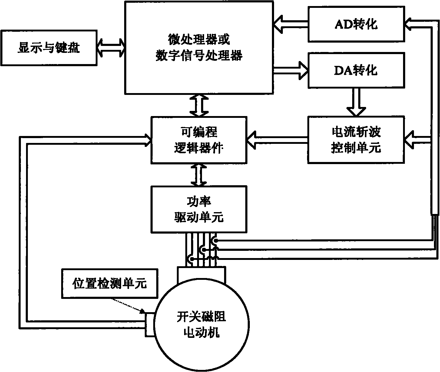
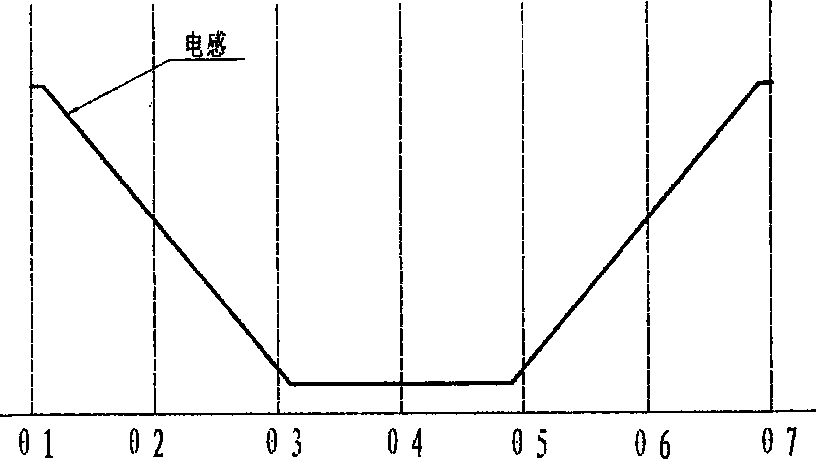
[0029] combined with figure 1 to attach Figure 6 The technical scheme of the present invention is described in detail:
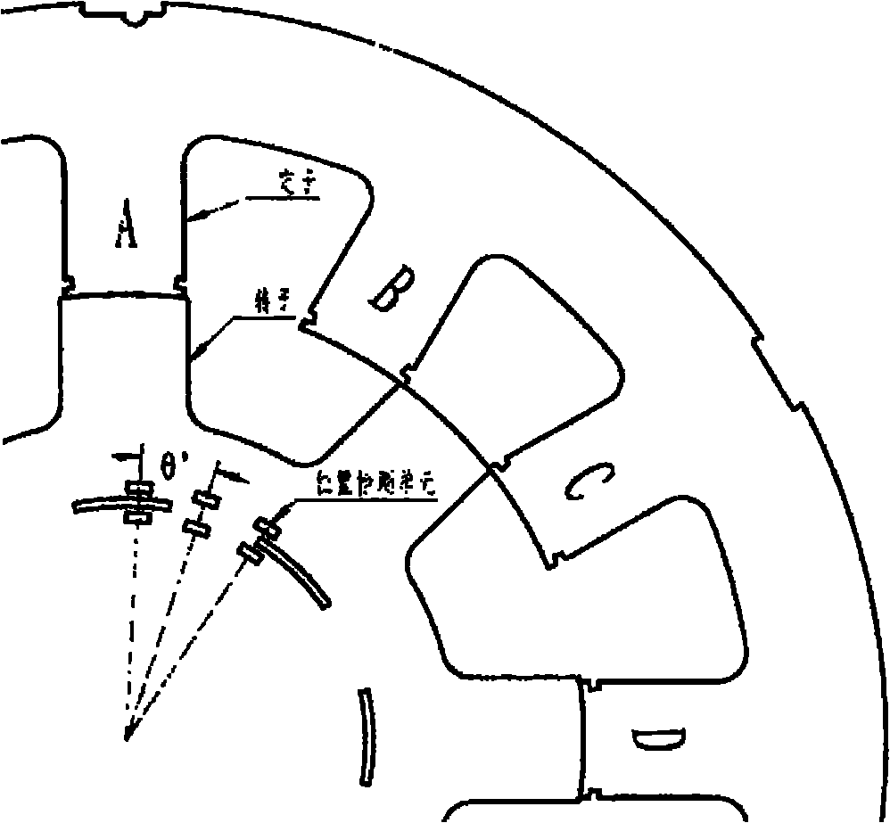
[0030] 1. Determination of the angle between the sensors: according to the formula Calculate the angle between the sensors, where m is the number of switched reluctance motor phases, N s is the number of stator poles, N r is the number of rotor poles. For a 12 / 8-pole switched reluctance motor, considering factors such as cost and implementation complexity, k is 0, θ g Take 15°. The sensor can choose photoelectric sensor or hall sensor. Such as figure 2 shown;
[0031] 2. The steps to determine the relative position between the position detection unit and the shading disc of the switched reluctance motor are: energize one phase winding of the switched reluctance motor, make the stator and rotor of this phase in an aligned position, and set the signal of the sensor at the shading position as 1. The non-shading position signal is 0, adjust the relat...
PUM
 Abstract
Description
Claims
Application Information
 - R&D
- Intellectual Property
- Life Sciences
- Materials
- Tech Scout
- Unparalleled Data Quality
- Higher Quality Content
- 60% Fewer Hallucinations
Browse by: Latest US Patents, China's latest patents, Technical Efficacy Thesaurus, Application Domain, Technology Topic, Popular Technical Reports.
© 2025 PatSnap. All rights reserved.Legal|Privacy policy|Modern Slavery Act Transparency Statement|Sitemap|About US| Contact US: help@patsnap.com


