

Heating-element unit, and heating device
A heating element unit and heating element technology, applied in the direction of electric heating device, ohmic resistance heating, heating element shape, etc., can solve problems such as difficult setting of the resistance value of the heating element, carbon fiber breakage, resistance value deviation in the length direction of the heating element, etc.
- Summary
- Abstract
- Description
- Claims
- Application Information
AI Technical Summary
Problems solved by technology
Method used
Image

Examples
Embodiment approach 1
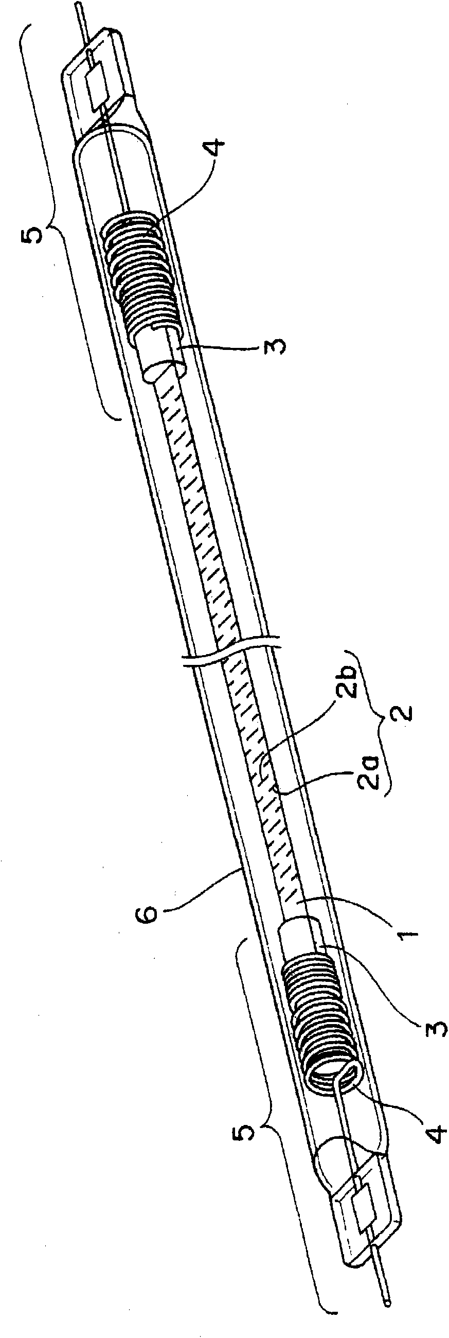
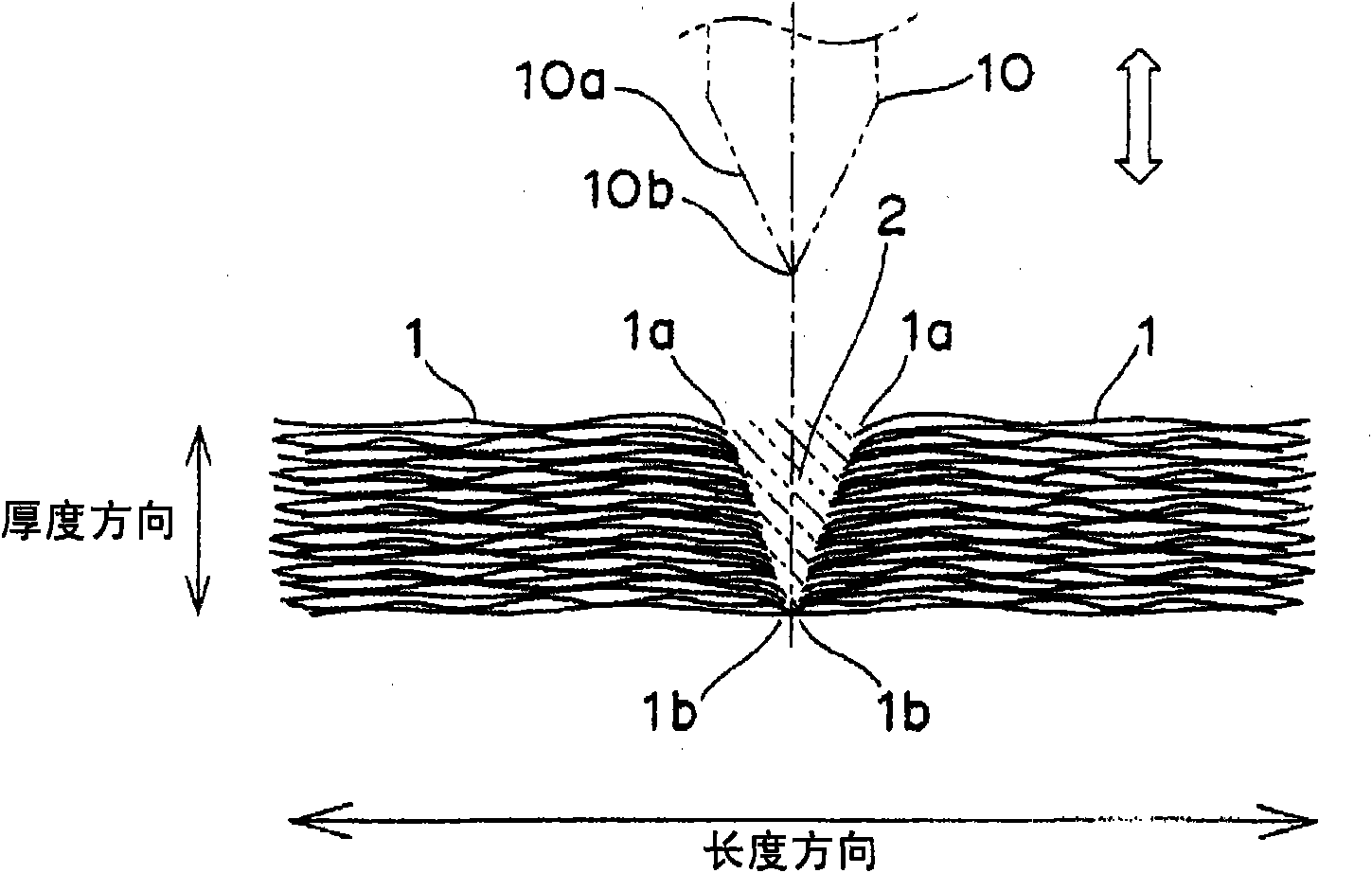
[0087] Regarding the heat generating unit according to Embodiment 1 of the present invention, using Figure 1 to Figure 9 Described below. In the heat generating unit according to Embodiment 1, the heat generating body is constituted by a film plate material in which a plurality of layers mainly composed of a carbon-based material is laminated with gaps interposed therebetween. That is, in the film sheet material, a plurality of layers are laminated with gaps in the layer thickness direction, and have flexibility. This thin film plate material has opposite tape surfaces constituting its front and back surfaces, and is formed into an elongated tape shape. In addition, a current suppressing portion serving as a current suppressing mechanism for suppressing a current flowing in the longitudinal direction is formed in the strip-shaped heat generating body.
[0088] figure 1 It is a perspective view which shows the heat generating unit of Embodiment 1. The heating element 1 for...
Embodiment approach 2
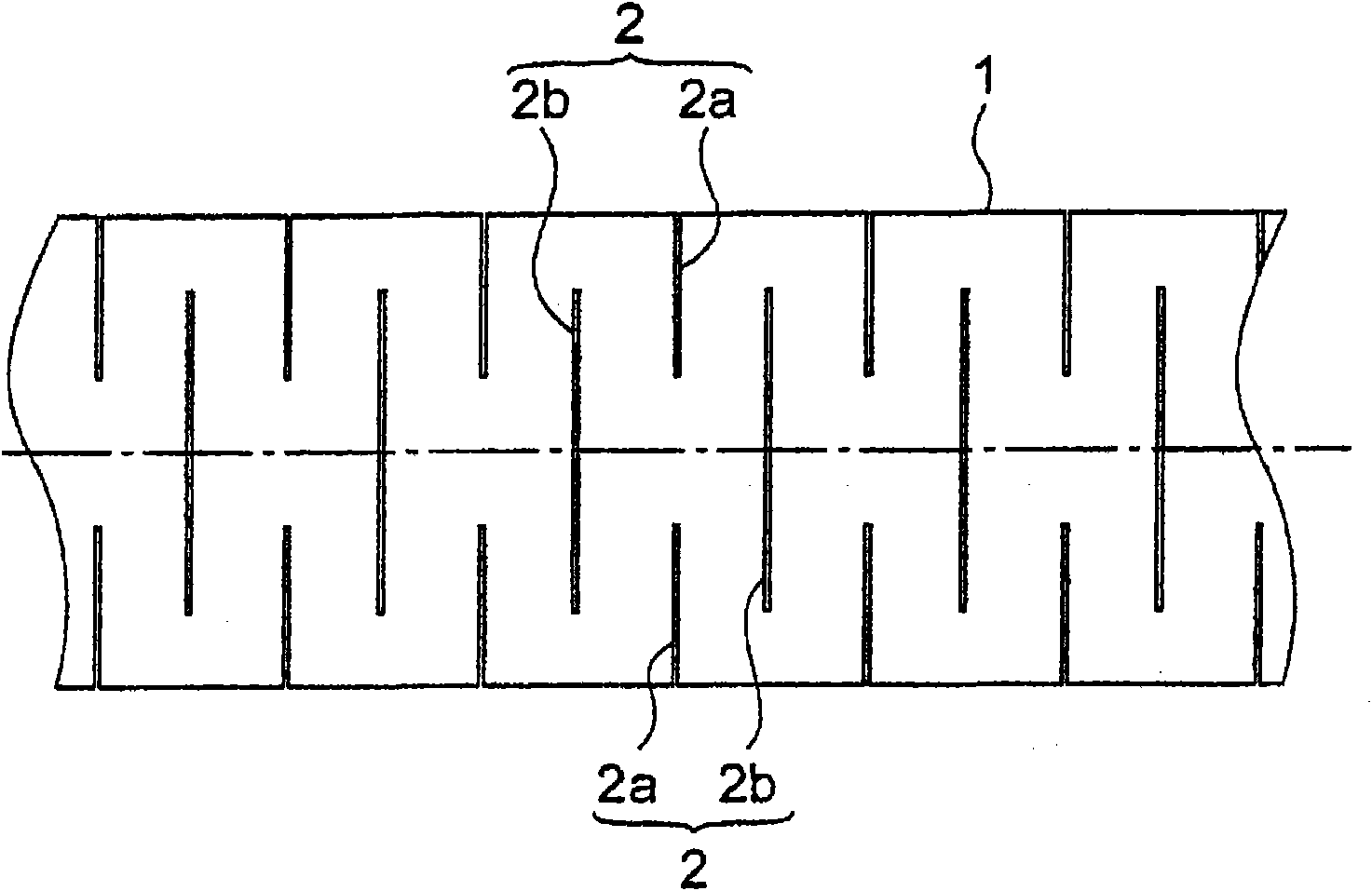
[0133] Next, use Figure 10 A heat generating unit according to Embodiment 2 of the present invention will be described. The heat generating unit according to the second embodiment differs from the heat generating unit according to the first embodiment described above in the cutting pattern of the current suppressing portion in the heat generating unit. Other points in the second embodiment are the same as those of the heat generating unit in the first embodiment. Therefore, descriptions repeated in the heat generating unit of Embodiment 2 below refer to the description of the heat generating unit of Embodiment 1, and different points will be described. In addition, in the description of the heat generating unit according to the second embodiment, the elements having the same functions and structures as those of the heat generating unit according to the first embodiment are denoted by the same reference numerals.
[0134] Figure 10 It is a plan view showing the current sup...
Embodiment approach 3
[0144] Next, the use of the heating element unit in Embodiment 3 of the present invention Figure 11 Be explained. The heat generating unit according to Embodiment 3 differs from the heat generating unit according to Embodiment 1 in that the cutting pattern of the current suppressing portion in the heat generating body is different. Other points in the third embodiment are the same as those of the heat generating unit in the first embodiment. Therefore, in the following description of the heat generating unit of Embodiment 3, the description of the heat generating unit of Embodiment 1 is cited repeatedly, and different points will be described. In addition, in the description of the heat generating unit according to Embodiment 3, elements having the same functions and structures as those in the heat generating unit according to Embodiment 1 are denoted by the same reference numerals.
[0145] Figure 11It is a plan view showing the structure of the current suppressing part ...
PUM
| Property | Measurement | Unit |
|---|---|---|
| Thickness | aaaaa | aaaaa |
| Density | aaaaa | aaaaa |
| Thermal conductivity | aaaaa | aaaaa |
Abstract
Description
Claims
Application Information