

Dye with low energy level difference, intermediate and preparation method and application thereof
An intermediate and low-energy technology, applied in the field of dye-sensitized solar cell materials, can solve the problems of difficult purification, high price, and difficult commercial application, and achieve high photoelectric conversion efficiency
Inactive Publication Date: 2010-10-20
PEKING UNIV
View PDF5 Cites 8 Cited by
- Summary
- Abstract
- Description
- Claims
- Application Information
AI Technical Summary
Problems solved by technology
At present, metal complex dyes based on ruthenium have encountered relatively large bottlenecks in terms of material improvement and device efficiency; in addition, due to the high price of ruthenium metal complexes, purification is difficult, and it is difficult to achieve large-scale commercialization. application
Method used
View moreImage
Smart ImageViewing Examples

Examples
Embodiment 1
Embodiment 2
Embodiment 3
Login to View More PUM
 Abstract
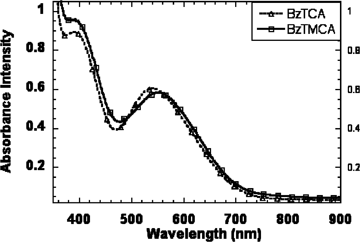
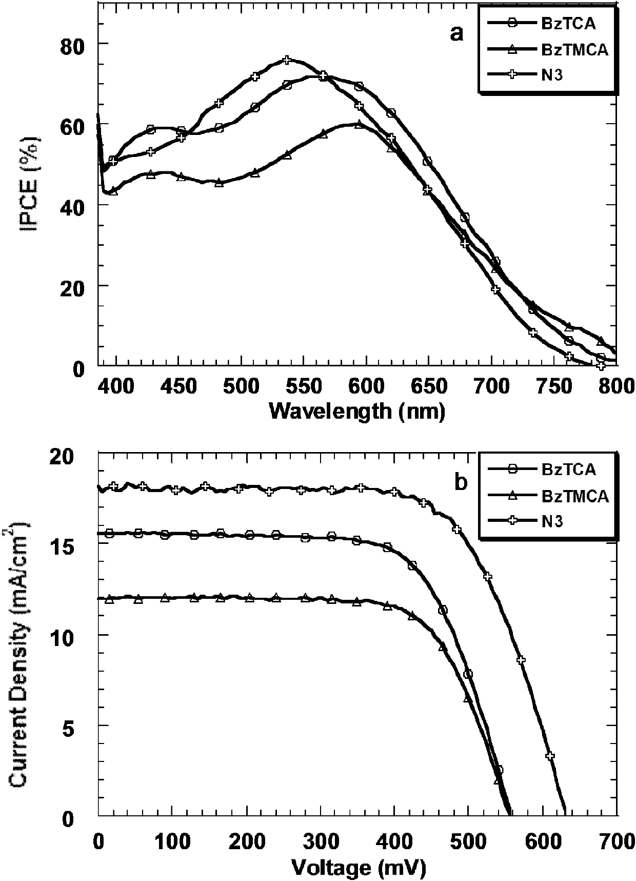
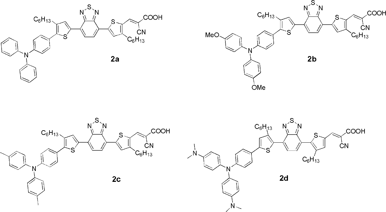
The invention provides a organic molecular dye with low energy level difference used in an organic dye-sensitized solar cell, a dye as shown in Formula 1. Due to the diazosulfide, the multi-level donor-acceptor structure in molecules and the electron withdrawing and releasing effect in the molecules, the dye has a broader absorption spectrum which can reach 800nm. The dye is one of the existing gmaterials with the broadest spectrum for absorption of sunlight in the dye-sensitized solar cell. Flexible chains in the molecules can not only improve the solubility of the molecules, thereby reducing difficulties in synthesis, purification and processing, but also can reduce the aggregation of the molecules in the device, thereby reducing the risk of hole-electron recombination. The structure and photophysical properties of the dye have large control space. The dye-sensitized solar cell with the composition with the low energy level difference as the sensitizing dye has high photoelectric conversion efficiency which can reach 9 percent to the maximum and is at the international advanced level. The Formula 1 is as follows.
Description
technical field The invention relates to the field of dye-sensitized solar cell materials, in particular to a new type of organic small molecule dye with low energy level difference containing benzothiadiazole. Background technique The history of the development of organic solar cells is relatively early, but relatively speaking, due to the low efficiency, there is still a long way to go for practical use, and the highest efficiency is still less than 8% of the minimum value of commercialization. In 1991, M. and others proposed a new type of photovoltaic cell with dye-sensitized titanium dioxide nano-film as the photoanode, called a battery, which uses titanium dioxide nano-film as a carrier and bipyridyl ruthenium (II) complex For sensitizing dyes, the energy conversion efficiency reaches 7%, which greatly stimulates people's research enthusiasm. In 1993, M. et al reported again the dye-sensitized nano solar cell with a photoelectric conversion efficiency of 10%. In 2001, ...
Claims
Login to View More Application Information
Patent Timeline
 IPC IPC(8): C09B23/14C09B57/00C07D417/14H01G9/20H01M14/00H01L51/42
CPCY02E10/542Y02E10/549Y02P70/50
Inventor裴坚唐铮铭雷霆
OwnerPEKING UNIV